


14
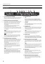
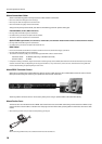
Part Names and Functions
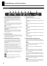
fig.rear-panel.eps
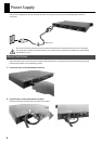
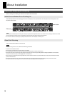
1. AC IN Connector and Cord Hook
This is for connecting the included power cable. Use the cord
hook to secure the connected power cable in place (p. 8).
2. REAC SPLIT OUT Connector and Indicator
This connector is exclusively for output to REAC devices. The
indicator flashes when communication with a connected
REAC device has been established. It lights up steadily
during standby.
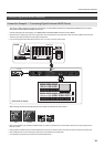
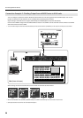
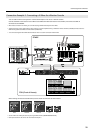
For information on connecting a REAC device, refer to
“Connecting MADI/REAC Devices” (p. 19).
* The REAC SPLIT OUT connector supports REAC EMBEDDED POWER.
It can supply power to M-48, S-0808, or other REAC-powered device
via a REAC cable.
The EMBEDDED POWER indicator on the front panel lights up when
a device powered by REAC EMBEDDED POWER is connected and
receiving power from the S-MADI.
REAC master or slave devices cannot be connected to the REAC
SPLIT OUT connector. Only a REAC split device or a REAC splitter
such as an S-4000D or S-4000-SP can be connected.
3. REAC MAIN Connector and Indicator
This connector is for input and output of REAC signals. The
indicator flashes when communication with a connected
REAC device has been established. It lights up steadily
during standby.
For information on connecting a REAC device, refer to
“Connecting MADI/REAC Devices” (p. 19).
* The REAC MAIN connector does not support REAC EMBEDDED
POWER. Do not connect equipment that requires power to be
supplied over the REAC cable.
For REAC signals to be input and output correctly, the mode settings
for all connected REAC devices must be made correctly.
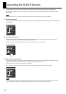
Use the [SELECT] button at REAC MAIN section to set appropriate
REAC mode for S-MADI. For information about setting the REAC
mode on your REAC devices, refer to the owner’s manuals for the
respective products.
4. CH OFFSET Switch
1-40
This connects REAC channels 1 through 40 with MADI
channels 1 through 40. Signals on MADI input channels 41
and beyond are sent (thru-out) to MADI output channels 41
and beyond.
41-56 (64)
This connects MADI channels 41 through 56 or 64 with REAC
channels 41 through 56 or 64.
5. CH MODE Switch
This sets the maximum number of MADI channels for input
and output. Set this to correspond to the mode setting of
connected MADI device.
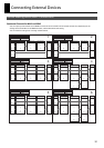
The connected MADI and REAC channels differ depending on the
settings of the CH OFFSET and CH MODE switches. Refer to
“Connected Channels for MADI and REAC” (p. 17).
6. OUTPUT Switch
To send (thru-out) the signal coming in from MADI IN
connectors to the MADI OUT connectors, set this to [THRU].
To output MADI signal derived from REAC, set this to [OUT].
7. MADI Input/Output Connectors (BNC)
These are BNC-type connectors for MADI input and output.
For input from the BNC connector, set the INPUT switch to
[BNC].
If the frequency tolerance is more than +/-40 ppm, the S-MADI may
be unable to perform conversion accurately. If the frequency
tolerance of the MADI device you are using is more than +/- 40 ppm,
connect a word-clock generator or other external source device and
set the CLOCK SOURCE to [WORD CLOCK].
8. INPUT Switch
This switch selects the connector for MADI input. Select
either [BNC] or [OPTICAL].
* MADI signals are output from both the BNC and optical MADI OUT
connectors regardless of the setting of the INPUT switch.
9. MADI Input/Output Connectors (Optical)
These are optical-type connectors for MADI input and
output. For input from optical connector, set the INPUT
switch to [OPTICAL].
Rear Panel
1234
5
6 7 8 9 10