


SECTION 2
TEST
MODE
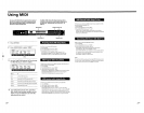
• This product uses a microcomputer and is equipped with a· MIDI interface for musical instruments and computers, and it has
specifications that make possible rewriting
of
the internal memory with external MIDI equipment.
Due to this, when required, the internal data can be rewritten by the use
of
external equipment, etc., and in case the internal data.should
break down at the time
of
repair (Example: when the power
is
cut oft), it may happen that the operation becomes unstable. Therefore,
when carrying out
service, make sure to pay attention to the following matters.
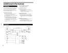
< Inspection when carrying out repair>
A self-test mode function has been provided to carry out inspection
of
each function without having to use a special jig when the repair has
been completed. Make absolutely sure to carry out these inspections before returning the unit to your customer.
< Regarding
the
test mode>
All
of
the inspections should be carried out, but in case some
of
them have already been completed they may be skipped upon proper
judgment.
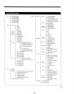
Subject
1.
Entering the test mode.
• Initialization
of
the memory
2. Inspection
of
each function
(No.1)
• Battery
• Pedal
•
Jog&Shuttle
• Switch
Operation and Display
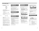
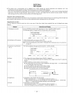
Turn the POWER switch ON while depressing the 3 keys
of
[BANK], [EDIT] and [C].
The following display will appear and the test mode menu will be activated.
r-----------------------------l
I
TEST
MODE MENU I
I I
I > Initialize User Memory? I
I YES NO I
I I
[EDIT] [ A ]
[
B]
[C]
[D]
[
E]
[F]
[EXIT]
1)
When initializing the user memory, select YES.
2) When you do not want to initialize the user memory, select NO.
Note:
Concerning initialization, please refer to <Examples when initialization has to be carried out>
on page 16.
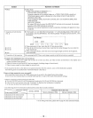
The following display will appear and test mode No. 1 will be activated.
r-----------------------------l
I
TEST
MODE 1 * 1 I
I
----------
I
I Battery [3.0] I
: PDL 1 [ ] PDL 2
[]
J & S [ ] :
:SW[
] :
[EDIT]
[A
]
[
B]
[C]
[D]
[
E]
[F]
[EXIT]
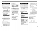
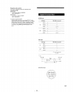
1) The voltage
of
the internal lithium battery (BA601)
is
displayed.
As the data
of
the internal SRAM cannot be maintained
if
the voltage
is
lower than 2V, replace the
BA601.
2)
PEDALl/pEDAL2
terminal (check on the rear panel).
• The pedal terminal
AID
conversion value
is
displayed in the range
of
000 - 127 within brackets
[ ] by adding the circuit shown below.
• Turn the semi fixture and confirm that the figures change.
•
If
not especially required, this procedure may be skipped.
•
If
there
is
no connection at all, 127 will be displayed.
tOOk Q RES,
ADJ
~
1
--P-HO-N-E-P-/Uglll-----.......,I~
i
To
peda/termina/
3) Checking the Jog & Shuttle dial (front panel)
• When rotating the dial, " * " will be displayed within the brackets [ ].
When turning the Jog dial once to the left and once to the right, the brackets [ ] will be fully
filled
by"
* " when turning the Shuttle dial fully to the left and right.
4) Checking the switch (front panel)
When pressing the switch,
" * " will be displayed within the brackets [ ].
When fully turning the switch, the brackets [ ] will be fully filled by
" * " .
-
17-