


~
Understanding
the
Signal
Flow
This
unit
takes
in
audio
signals
from
two types
of
input
jacks
(digital
and
analog), processes
them
using
various
internal
blocks,
and
outputs
them
through the analog and digital output
jacks.
To
make
the
most
of
this
unit,
it
is
essential that
you
have
a
firm
understanding
of
the
audio
signal
flow.
This
section provides
an
explanation
of
the internal
blocks
and
how
they
process
the input
and
output audio signals.
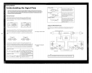
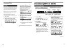
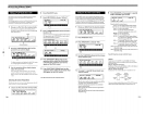
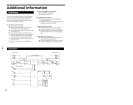
Block
and
structure
The audit) signal processor in this
unit
is
divided
into
two
parts, BLOCK
1\
and
BLOCK
B.
Each
of
tlwse blocks is
composed
of
an
EQ BLOCK
and
(\n
FX
(dfect)
BLOCK. Thl'
EQ
BLOCK
works
as
anl'qualizer.
The
FX
BLOCK
contains
a large
number
of multi·dfe'cls.
BLOCK
A
~
",OC",
FX
BLOCK
FX
BLOCK
~
(reverb. pitch
EQ
(reverb. pitch
BLOCK
shifter. chorus.
I 'LOCK I
~;ft"
<ho,.,.
etc.
..
)
etc
...
)
The positioning of the EQ block
and
the
rX.block is
determined
when
editing
the
EQ
BLOCK by c1wosing
either
"Pre"
or
"Post"
in the I Model
parameter.
In
other
words.
you can c1wt)se.
independently
within BLOCK A
and
BLOCK
B.
wether
to
add
the
effect
to the
sound
coming
from the equalizer,
or
equalize
the
sound
produced
by the
effect.
When you select
"Pre"
IEQlfFxl
...
~
...
~
...
When
you
select
"Post"
fFxI
IEQl
...
~
...
~
...
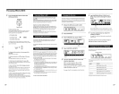
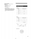
It's
abt)
l1l'cessary to
dett'rmine
the
positions
of
the larger blocks. BLOCK
1\
and
BLOCK
B.
Thdr
pt)sitioning, the
way
they arc connected, is called
the
"structure."
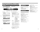
Set
the
structure
according to
the
kind
of
sound
you
want
to make.
The
structlire screen
not onl\' lets
vou choose the
structure
type
(see
the
following
chartl.
but
also lets you
adjust the
output
I"\'el for each block
(represented
in the
chart
by
the
MIX
BLOCK).
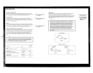
SERIAL
A'"
B (SERll)
IN
OUT
ch
I
-;
~~.~~~
H'~,~'
U~~;~:l-1'-~~~'~Ch
I
ch
2---'
A
1_
BLOCK
W.
B I
BLOCK
ch 2
: .... . ............
1.
......
__
1
...
_
....
_
For exampl".
if
you set the
BLOCK
A as an
intense f1anger, ilnd
:->t't
the
BLOCK
Has
tht'
l<ugl'st
i1vailaole rcvl'rb (sec page
17
for
dC'lail.
on
hol',,·
to
edit
effects)
(For
information
I
SERIAL
B
...
A
(SERI
2)
I
:~~~;~,i~;p~f:~'~:~.~;~~;~dll~~~·;~:'~:'"c';:~:~:~r:nd
IN
OUT
ch
1-;
B~~~~
l-r·~;x-l-4·;~;;:J~···~~~··
ch I
ch
2
---'
B
!-o!
BLOCK
U A
BLOCK
ch 2
: •........
_1
L
..
_ ..•
.J
L_.___
_
"Preset Memory Catalog.")
You
C(lll add
n,'vl'rb
to
the sound produced by
the f1anger effect, or you can flange the sound
produced
by the reverb effect.
...
See
page
17
to
EDIT
an
effect.
...
See
page
19
to
change
the
structure.
PARALLEL
'(PARA)
C~NI~'
1
Bl~CK
l-fl
~IX
F:::
,.
BLOCK
ch 2
Bl~CK
]=1
ch 2
DUAL (DUAL)
IN
OUT
ch
1-9
Bl~~
]~
'~~XFCh
I
BLOCK
r-J
BlD.·
CK
I.
..
. ch 2
Ch2--~i
~
__
MORPHING (MORPH)
C:~I-1B.lOCK
..
·.I-1
~I~
..
l-.
~~~
Ch2-1.
A
[BLO.CKJ_Ch2
Setting
the
INPUT/OUTPUT
levels
This
strll<:tun
..
' Ids
y~)U
.lpply
t..'ffl'l..'tS,
like
fI.\I'lhl·r
.1Ild
rl'vl'rh,
sl'p.lr.\tdy
.lnt.!
thl'n
mi\
tlwm
bdort..'
output. In this
("SC,
tlll..·rt..
..
~
no
undulatioll from
till..'
t).lIlgl'r
in
thc rcverb,
This strw
..
-turl.'
lets you isol.ltt..'l·h 1
Mld
(h
2,
For
t.':\.lmplc,
you Cilll connect il
~lIit,u
il)
dl
1
imd
,l
drum
m.Khint.'
to
ch
2,
tht..·n
,ldd
,l
tl.lIlgt..·r
dfl'el
to
the guit.u .lnd
.t
rt.'vt..'rb
I..'Ht.'Ct
to
tht..'
drum m.Khinc.
This
strw.:ture
Ids you make
sl'.lI"nless
Ch.lngl'S
bl'twt..'t...'1l
dfl,C'ts
stOfl'J
in
thl.'
mt..'Il\Of\'
b.mks
In
otllt..'r
won.b,
it
kt.'t.·ps
tht..'
(Urrl'nt
~t't't.....:t
from
:,uJdt..'nly
cutting
l)ut
",ht..'n
you
dl.1IlgL'
tl)
.uwthl'r
dfl'd,
ror lil,tails
01\
morphinh'
SL'1.'
"rvh)rphing"
on p.lgl'
16.
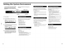
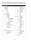
This ch.ut
shows
the
OVl.'r.liJ
SiglM}
flow rl'i.1tionship bet\\'l'l.'n this unit's inputs
,1nd
outputs,
Tht.'
following infurnl.ltion is
.1n
oVl'r\,iew
of
,)11
you
Ill'ed
to
know fl'gtlrt.iing this unit's inputs and
ot\tputs.
DIGITAlINPUT ATIENUATION
lEVEl
"~~~
D :
::
"'''''''''''''''''
EQ
BLOCK
EffECT
BLOCK
BYPASS:SW
'Q._----------------"\
You can use
the
effector
as
an
AID
or
DIA
converter
by
turning
off
all
the
effects.
DIGITAL
OUT
ANALOG OUTPUT
~CHl
BALANCED
~CH2