


~
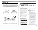
Getting Started
Names
and
Functions
of
Parts
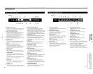
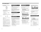
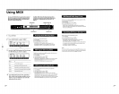
Front
panel
2 3 4 5
17 16 15
14
POWER
ON/OFF switch
Press this switch to
turn
the
power
on
and
off. Turning
on
the power on recalls the last used memorized effect
and
activates play mode automatically.
2 INPUT level adjustment knob
Turn
the knob to the left
or
right to adjust the input level.
Adjustments can
be
made
independently for each
channel. The outer knob to adjusts
channell
(CH
1)
and
the inner knob adjusts channel 2 (CH
2)
(page
14).
3 OUTPUT level adjustment knob
Turn
to
the left
or
right to adjust the
output
level from the
output
jacks.
4 Input level meter
Indicates the strength of the
input
signal from -36 dB to
CLIP (overload) with green, orange, and rcd indiCators
(page
14).
5 Memory number display
window
Displays the memory
number
of current effect. 99
different effects are stored in each of the
PRESET memory
banks and
up
to
99
effects can be stored in each of the
USER
memory banks.
6 Multi display
Displays various information, such as the name of the
currently selected effect,
parameter
values, and messages.
7 Number buttons
Use these buttons'to recall effects from the currently
chosen memory bank directly
and
input exact
parameter
values (page
14).
Use
...
or T while holding
down
ENTER/SHIFf
to make
incremental adjustments to parameter values
(poge
14).
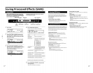
8
SAVE
button
Use this button after chonging parameter values to save a
custom
effect in one of the
USER
memory banks
(page
22).
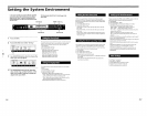
9
SYSTEM
button
6
EN
Use this button to access the system mentIS and customize
the
effecttlr's t'perating environment (pages
24
and
25).
6
7 8 9 10
13
12
11
10
10 Operation dial/Shuttle ring
Use to select
memory
numbers from the currently
selected memory
bank
and make adjustments to
parameter settings. The operation dial lets you advance in
one-step increments. The jog dial lets you
advance
rapidly
in larger increments, The rate of advance (or value
change) changes according to the angle of the shuttle ring.
11
ENTER/SHIFT button
Use this button to enter a memory
number
or
parameter
value
input
with the numeric buttons (page
14).
Hold
down
while pressing the
...
or T button to make a
one-step adjustment to a memory
number
or
a parameter
value (page
14).
12
EXIT
button
Press after
or
during
a setting procedure to return to the
previous screen
or
mode,
or
to de-select an active
parameter
on
the play screen,
13
FUNCTION A-F buttons
Use to select the items displayed above the respective
buttons.
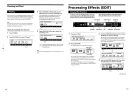
14 EDIT/PAGE button
Press
during
play
mode
to access the edit screen
and
make changes to the current effect (page
17).
Press to display different pages of multi-page
menus
(page
17).
15 BANK/COMPARE button
Press to select the memory bank containing the effect you
desire (page
14).
In edit mode, press to
compare
fllterations
in
effect parameters
to
the unaltered effect
(page
18).
16 BYPASS/MUTE button
Press to route the signal around the effect processing
circuitry so that the signal being input
is
output
unchanged (bypass), or
to
completely cut
output
from the
effector (mute), (see page
15).
17 Memory bank indicators
Indicate the currently selected memory bank: PRESET
1,
PRESET
2,
USER
1,
or
USER
2 (see page
14).
Narnes
andiFuractiol'ls
of
Parts
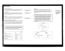
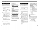
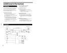
Rear
panel
AC
power
cord socket
For connecting the effector to an AC
power
outlet using
the supplied AC
power
cord.
2 MIDI THRUIOUT terminal
For sending
and/
or
relaying MIDI
command
signals
frQm
the effector to other components
(see page
26
to select THRU
or
OUT).
3 MIDI
IN
terminal
Input for MIDI
cOll,1mand
Signals. Use a commercially
iWililable MIDI cable to connect this terminal to
another
component's MIDI
OUT
(or THRU) terminal.
4
PEDAL
1 and 2
jacks
Inputs for pedal switches
and/or
volume control
(pages
21
and
25).
5 DIGITAL I/O terminal
Use digital interface cable RK-V77 A (for AES/EBU)
or
I{K-
V77S
(for SPDIF) to
make
digital connections between
the effector
and
other
components
(pages
8,
12,
13
and
29).
11
10
6
BALANCED
OUTPUT
jacks
Balanced
output
jacks for channel 1 and channel 2
(pages 9 and
10).
7 STANDARD OUTPUT
jacks
Standard
output
jacks for
channd
1 and channel 2
(pages 9 and
10).
8 STANDARD INPUT
jacks
Standard input jacks for channel 1 and channel 2
(pages 9 and
10).
9
BALANCED
INPUT
jacks
Balanced input jacks for channel 1
and
channel 2
(pages 9 and
10).
1Q
INPUT level selector switch
Use to set the
input
level of the STANDARD INPUT jacks
(8)
to match the
output
level of the connected equipment.
You can select a
-20
dB
or
+-1
dB input level.
11
OUTPUT level selector switch
Use to set the
output
level of the STANDARD OUTPUT
jacks
(7)
to match the input level of the connected
equipment. You
can select a -20 dB or
+-1
dB
output
level.
7EN
G)~
mO
Z-f
m-
:0
0
~Z
r
.....
S·
-l
C/l
:J
r+
--
-,
C/l
C
o
C/l
~.
CD
o 0
:::l
g-
3
.:::l
ro
-.
:::l
(J)
C
ro
CD
;-X
r+
~
~
CD
0...
-+.
a
3