


SRP-X500P RS-232C Interface Manual
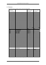
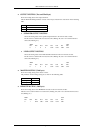
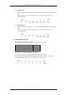
• SETUP STATUS
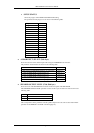
Shows the progress of the FEED BACK REDUCER setting.
The parameter and the progress are as shown in the following table.
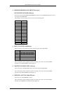
Progress
Stopped (finished) 0x30 (‘0’)
1 0x31 (‘1’)
2 0x32 (‘2’)
3 0x33 (‘3’)
4 0x34 (‘4’)
5 0x35 (‘5’)
6 0x36 (‘6’)
7 0x37 (‘7’)
8 0x38 (‘8’)
9 0x39 (‘9’)
10 0x3A (‘:’)
11 0x3B (‘;’)
12 0x3C (‘<‘)
13 0x3D (‘=‘)
14 0x3E (‘>‘)
15 0x3F (‘?’)
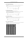
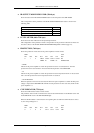
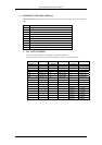
♦ AV/RGB INPUT SELECT (56th byte)
Shows the selection of the channel input from among the AV/RGB INPUT connectors.
The parameter and the channel are shown in the following table.
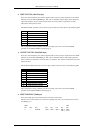
Channel
OFF (All the AV RGB SELECT buttons are turned off.) 0x30 (‘0’)
A (The AV RGB SELECT A button lights up.) 0x31 (‘1’)
B (The AV RGB SELECT B button lights up.) 0x32 (‘2’)
C (The AV RGB SELECT C button lights up.) 0x33 (‘3’)
D (The AV RGB SELECT D button lights up.) 0x34 (‘4’)
E (The AV RGB SELECT E button lights up.) 0x35 (‘5’)
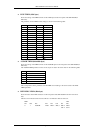
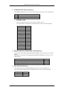
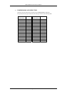
♦ SPEAKER OUTPUT LEVEL (57th, 58th byte)
Shows the level of the SPEAKER OUT controls on the front panel of the SRP-X500P.
The SPEAKER OUTPUT LEVEL parameter consists of the 2 bytes of data in the order shown in the
following table.
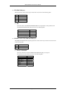
Byte Parameter
1st SPEAKER OUTPUT CH1/2 LEVEL
2nd SPEAKER OUTPUT CH3/4 LEVEL
The correspondence of the parameter with the speaker output level is the same as that of the LEVEL
parameter of the REMOTE 1-6 LEVEL command (page 10).
Page 32/43