


SRP-X500P RS-232C Interface Manual
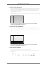
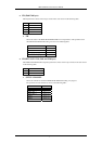
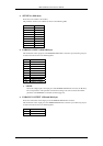
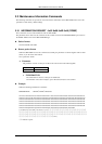
♦ SCENE No. (84th byte)
Shows the scene number to be recalled.
The parameter and the scene number are shown in the following table.
SCENE No.
None 0x30 (‘0’)
1 0x31 (‘1’)
2 0x32 (‘2’)
3 0x33 (‘3’)
4 0x34 (‘4’)
5 0x35 (‘5’)
6 0x36 (‘6’)
7 0x37 (‘7’)
8 0x38 (‘8’)
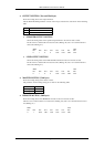
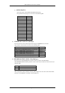
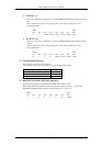
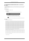
♦ PARALLEL INPUT (85th-94th byte)
The information on the input pins of the REMOTE PARALLEL connector is provided using 10 bytes
of data in the order shown in the following table.
Byte Parameter
1st INPUT 1 LEVEL
2nd INPUT 2 LEVEL
3rd INPUT 3 LEVEL
4th INPUT 4 LEVEL
5th INPUT 5 LEVEL
6th INPUT 6 LEVEL
7th INPUT 7 LEVEL
8th INPUT 8 LEVEL
9th INPUT 9 LEVEL
10th INPUT 10 LEVEL
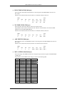
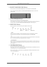
• LEVEL
Shows the voltage input to the input pins of the REMOTE PARALLEL connector (in dB units).
The correspondence of the parameter with the level setting is the same as that of the LEVEL
parameter of the REMOTE 1-6 LEVEL command (page 10).
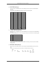
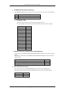
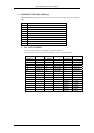
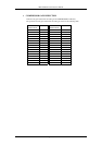
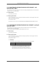
♦ PARALLEL OUTPUT (95th and 96th byte)
Shows the on/off status of the output pins of the REMOTE PARALLEL connector.
The information on the output pins of the REMOTE PARALLEL connector is provided using 2 bytes
of data in the order shown in the following table.
Byte Parameter
1st OUTPUT 1-6
2nd OUTPUT 7-10
Page 35/43