


SRP-X500P RS-232C Interface Manual
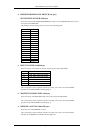
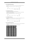
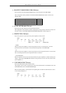
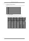
♦ IR OUTPUT MODE INDICATOR (59th byte)
Shows the status of the IR OUTPUT MODE button on the front panel of the SRP-X500P.
The correspondence of the parameter with the IR OUTPUT MODE button status is shown in the
following table.
IR OUTPUT MODE
Normal operation (The button is turned off.) 0x30 (‘0’)
Transmission wait status (The button lights up.) 0x31 (‘1’)
Transmission in progress (The button flashes.) 0x32 (‘2’)
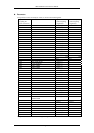
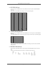
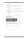
♦ LEVEL METER (60th-75th byte)
Shows the level meter indication of the input/output channels.
The configuration of the parameter and the correspondence of the parameter with the level meters are
the same as those of the LEVEL METER PARAMETER REQUEST command (page 21).
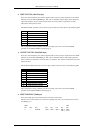
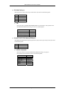
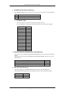
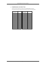
♦ PROTECTION (76th byte)
Shows the protection circuit status of the power amplifiers in 8 bits of data.
MSB LSB
bit7 bit6 bit5 bit4 bit3 bit2 bit1 bit0
0 1 0 CH3/4 CH3/4 CH1/2 CH1/2 DC
TEMP. IC TEMP. IC DETECTION
・TEMP.
The bit for the power amplifier is 0 when the protection circuit is not activated and 1 when the
protection circuit is activated due to increased internal temperature of the SRP-X500P.
・IC
The bit for the power amplifier is 0 when the protection circuit incorporated in the IC is not activated
and 1 when the protection circuit incorporated in the IC is activated.
・DC DETECTION
When the protection circuit is not activated, The bit for the power amplifier is 0. When the DC power
voltage is output to the SPEAKER CH terminals and the protection circuit is activated, the bit for the
power amplifier is 1.
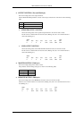
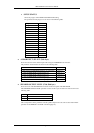
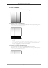
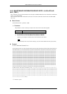
♦ CLIP INDICATOR (77th byte)
Shows the CLIP indicator status in 8 bits of data.
The parameter shown for this command is the status of the CLIP indicators in the BLOCK screen and
the OVER VIEW screen of the SRP-X500P Manager.
When the CLIP indicator is turned off, the corresponding bit is 0. When the CLIP indicator is turned
on, the corresponding bit is 1.
MSB LSB
bit7 bit6 bit5 bit4 bit3 bit2 bit1 bit0
0 1 0 0 CH 4 CH 3 CH 2 CH 1
Page 33/43