10
REMOTE PARALLEL Terminal
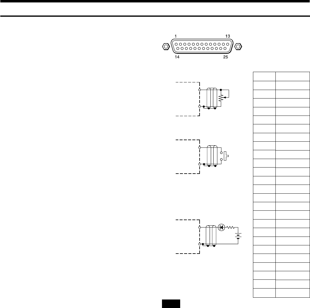
The REMOTE PARALLEL terminal enables the SRP-X700P to be
remotely controlled with a simple circuit connected externally to
this terminal.
Terminal shape : D-sub 25-pin, female
Recommended cable : Multi-core shielded cable for data
communication
Cable length : 50 m or less
INPUT terminal
You can set the functions of the respective terminals from the
PARALLEL INPUT FUNCTION setup box in the REMOTE
screen of the supplied SRP-X700P Manager software.
All faders and sound volume controls can be controlled from a
remote location by connecting a variable resistor as shown, in the
range of 0 to
–
∞ dB.
You can perform the following operations by adding a make contact.
• Input selection of LINE 4 system
• Muting
• Scene recall
• Sound volume adjustment (Up/Down)
• Controlling the AV equipment connected to the CONTROL S
terminal
• Power-ON/STANDBY selection of a projector
OUTPUT terminal
The turning ON conditions of the respective pins of the OUTPUT
terminal can be set from the following.
• Input selector state of LINE 4 system
• Turning ON the OVER and
–
∞ indicators
• Turning ON the scene recall button
• Generation of the Power-ON/STANDBY command of a
projector
You can select the ON conditions from the PARALLEL OUTPUT
FUNCTION setup box on the REMOTE screen of the supplied
SRP-X700P Manager software.
(D-sub 25-pin, female)
<Example of input circuit>
10 kΩ
Curve-B variable
resistor
GND
(Nos. 1, 14 and 25)
<Example of output circuit>
GND
(Nos. 1, 14 and 25)
Pin No.
1
2
3
4
5
6
7
8
9
10
11
12
13
14
15
16
17
18
19
20
21
22
23
24
25
Function
GND
INPUT1
INPUT2
INPUT3
INPUT4
INPUT5
INPUT6
INPUT7
INPUT8
INPUT9
INPUT10
INPUT11
INPUT12
GND
OUTPUT1
OUTPUT2
OUTPUT3
OUTPUT4
OUTPUT5
OUTPUT6
OUTPUT7
OUTPUT8
OUTPUT9
OUTPUT10
GND
SRP-X700P
SRP-X700P
40 mA MAX
N
SRP-X700P
24 V
MAX
0 dB
–
∞ dB
Note
• Do not apply any reverse voltage across the output terminal.
• Do not connect the shield cable of the REMOTE wire and the
GND wire to the terminal table or the like. It can cause
malfunction and noise.
• Install the REMOTE cable away from the dimmer, motor and
others.
Input terminal
(No. 2 to No. 13)
Output terminal
(No. 15 to No. 24)
Input terminal
(No. 2 to No. 13)
GND
(Nos.
1,
14 and 25)
How to Control the SRP-X700P from External Equipment
LED


