


7
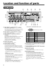
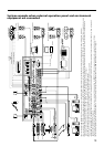
0 Video output terminals
The video signal that is selected by the LINE 4 SELECT
button on the front panel is output from this terminal. (The
video signal format is not converted from each other.)
• 5BNC output terminals
The RGB and component signal output terminals.
• VIDEO terminal
The composite signal output terminal.
• S VIDEO terminal
The S VIDEO signal output terminal.
qa CONTROL S OUTPUT 1 to CONTROL S
OUTPUT 4 terminals
You can control AV equipments connected to the LINE 3 IN
terminal and LINE 4 INPUT terminal by remote control
through these terminals.
Note
The AV equipment connected to the LINE3 IN terminal
cannot be controlled from supplied software User Control
Panel.
You can perform the basic operations of Sony DVD, VCR,
CD, MD and CD-R audio, such as playback, stop, fast forward
and rewind. You can select either the wired connection or the
wireless connection for each terminal from the SRP-X700P
Manager.
qs PROJECTOR CONTROL terminals
The SRP-X700P can controls a applicable projector and
plasma display connected to the video output terminals from
this terminal.
By default, connection to use the VPL-FX50 is set through
RS-232C.
• RS-232C terminal
This terminal is for a projector or plasma display having the
RS-232C terminal.
• CONTROL S IN/OUT terminal
The SRP-X700P can control a projector without the RS-
232C terminal through the CONTROL S.
When controlling a projector using the CONTROL S OUT
terminal, mixed use of the component signal and the RGB
signal is not possible.
qd REMOTE PARALLEL terminal
The parallel remote terminal contains 12 INPUTs and 10
OUTPUTs.
You can control the SRP-X700P from external remote
equipment using the INPUT parallel remote pins. You can
control the external remote equipment from the SRP-X700P
using the OUTPUT parallel remote pins. You can select the
functions of the respective terminals using the supplied SRP-
X700P Manager software.
qf REMOTE RS-232C terminal
The RS-232C remote terminal.
You can control the SRP-X700P with external equipment
connected to the RS-232C terminal from a remote location.
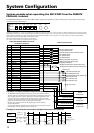
qg REMOTE USB terminal
You can connect a personal computer in which the supplied
software (SRP-X700P Manager and User Control Panel) is
installed, to the SRP-X700P through the USB terminal.
Note that the USB terminal on the front panel has priority if
the USB terminal on the front panel is being used.
qh ANT IN terminal
The antenna input terminal for the wireless tuner.
Connect a UHF antenna of the AN-820A (option).
9V power is supplied from this terminal as the power for the
antenna booster. Do not connect any antenna other than the AN-
820A, otherwise the system may not work or may cause failure.
Note
For details of installation and connection of an antenna,
thoroughly read the operating instructions supplied with the
antenna.
If the antenna is not installed correctly, it may cause defective
reception resulting in intermittent sound. Especially, if the
location cannot be changed easily after installing the antenna,
check the operations thoroughly prior to installation.
Connect the antenna using coaxial cable having the impedance
of 50 Ω. The maximum length of the cable is approximately
50 m with 5D-FB. Do not use the cable of a
75 Ω system such as 5C-2V, as its maximum length is half that
of the 5D-FB and it may cause a trouble.
If noise occurs:
There can be a case that a specific channel cannot be used due
to external noise or the noise caused by interference radio
wave depending on the installation location. In such a case,
find a channel that does not illuminate the RF indicator when
the wireless microphone power and the transmitter power are
turned off (i.e., the channel that is not adversely affected by
noise and interference radio wave). Use the unaffected
channel. Select the same unaffected channel for the wireless
microphone and the transmitter.
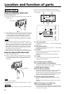
qj AC IN terminal
Connect the power cord supplied to this terminal.
qk + 48 V button
Press this button to supply the DC +48V condenser
microphone power to the MIC INPUT 1 to MIC INPUT 4
terminals. When this button is pressed ON ($), DC +48 V is
output.
By default, this button is set to OFF (4).
ql MIC/LINE selector button
You can select the input level of the MIC 5/LINE 1 IN and MIC
6/LINE 2 IN terminals with this button. (Refer to page 18.)
Also, when this button is set to the (+48 V) MIC ($) position,
the DC +48 V condenser microphone power is output
automatically.
By default, this button is set to LINE (4).
Notes
• The depressed position, which is the ON position, of both
the qk +48 V button and the ql MIC/LINE selector button
is lower than the face of the rear panel. The depressed ON
position is designed intentionally to prevent mis-operation.
• Before you make any attempt to disconnect and connect
cables or to press any of the +48 V button, MIC/LINE
selector button or other buttons, be sure to decrease the
input fader completely or to turn off the power.
w; CIRCUIT BREAKER
The circuit breaker works to turn off the main power of this unit
if an excessive current flows in the power supply of this unit.
If the circuit breaker trips, please contact your local Sony
Sales office or Dealer.