


4
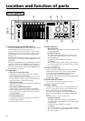
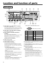
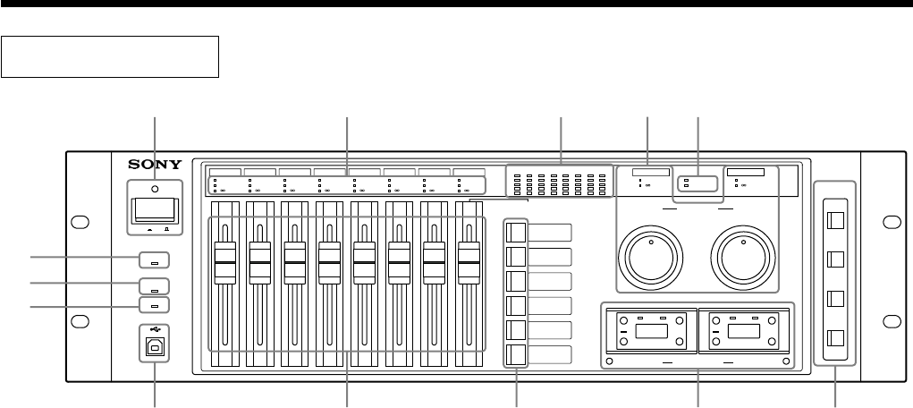
1 POWER button and POWER indicator
Pressing the POWER button turns on the power. The POWER
indicator lights in green when the power turns on.
You can switch the projectors and displays connected to the
SRP-X700P, to power-on state or to power standby state from
the SRP-X700P as they are interlocked by the SRP-X700P
Manager setup.
By default when shipped from the factory, the projectors and
displays powers are interlocked with the POWER button of the
SRP-X700P.
Turning on the POWER button of the SRP-X700P, sets the AV
equipment connected to the CONTROL S OUT terminals 1
through 4, to power-on state. Note that the AV equipment does
not enter the power standby state when the POWER button of
the SRP-X700P is turned off.
2 Input faders
• MIC1/WL1 and MIC2/WL2 faders
Adjusts the level of the signals supplied from the MIC1/
WL1 and MIC2/WL2 input terminals.
Either a wireless microphone or wired microphone can be
connected. When the wireless tuner receives the signal, the
wireless microphone is selected automatically.
• MIC3 and MIC4 faders
Adjusts the level of the signals supplied from the MIC3 and
MIC4 input connectors.
• MIC5/LINE1 and MIC6/LINE2 faders
Adjusts the level of the signals supplied from the MIC5/
LINE1 and MIC6/LINE2 input terminals. The MIC/LINE
selector button on the rear panel can be used to switch the
reference input level.
By default, LINE is selected.
• LINE3 and LINE4 faders
Adjusts the level of the signals supplied from the LINE3
and LINE4 input terminals.
These input faders are not the “moving” type.
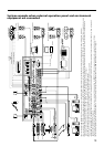
Location and function of parts
3 Input indicators
• SIGNAL indicator
The SIGNAL indicator lights in green when a signal is input
to each input terminal.
• OVER GAIN indicator
The OVER GAIN indicator lights in red when the input
level exceeds the GAIN LIMIT value that is set up by the
SRP-X700P Manager.
By default, the GAIN LIMIT is set to 10 dB.
•
–
∞ indicator
The
–
∞ indicator lights in yellow when no audio is output in
such cases as muting or when the INPUT fader is located at
the
–
∞ level position.
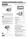
4 Tuner slots (WL 1/2)
This slot accepts the 800 MHz band wireless tuner unit WRU-
806B (option). It accepts up to two units. (For installation,
refer to page 8.) The WRU-806B Operating Instructions
provide full details on operating the tuner unit.
For operation of the tuner unit, read the WRU-806B Operating
Instructions thoroughly.
5 LINE 4 SELECT button
You can select a device to be connected to the input
connectors from 4A to 4F of LINE 4.
6 Master volume
With the master volume, you can control multiple faders that
are set as a single group. The faders to be controlled by the
master volume are set by the SRP-X700P Manager.
By default, the MASTER A is set to MIC1 to MIC4 input
faders, and the MASTER B is set to LINE1 to LINE4 input
faders.
The master volume is not the “moving” type.
• OVER GAIN indicator
The OVER GAIN indicator lights in red when the input
level exceeds the GAIN LIMIT value that is set by the SRP-
X700P Manager.
By default, the GAIN LIMIT is set to 10 dB.
•
–
∞ indicator
The
–
∞ indicator lights in yellow when no audio is output in
such cases as muting or when the INPUT fader is located at
the
–
∞ level position.
Front panel
MIC1/WL1 MIC2/WL2 MIC3 MIC4 MIC5/LINE1 MIC6/LINE2 LINE3 LINE4
MASTER
SCENE
RECALL
A
B
C
D
E
F
POWER
WL 1 WL 2
CLIP
PROTECTION
LOCK
USB
RS-232C
MASTER A MASTER B
-20
-10
-5
0
+3
-20
-10
-5
0
+3
2VU
1345678
VU
OUTPUT
SIGNAL
OVER GAIN
-
SIGNAL
OVER GAIN
-
SIGNAL
OVER GAIN
-
SIGNAL
OVER GAIN
-
SIGNAL
OVER GAIN
-
SIGNAL
OVER GAIN
-
SIGNAL
OVER GAIN
-
SIGNAL
OVER GAIN
-
OVER GAIN
-
OVER GAIN
-
AB
MIC TUNER
LINE 4 SELECT
ON OFF
A
B
C
D
1
9
0
qa
3867
qd452qs