


6
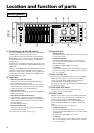
1 MIC INPUT 1 and MIC INPUT 2 terminals
The microphone input terminals.
The wireless microphone has the first priority when the tuner
unit is installed but you can use the wired microphone up until
you turn ON the POWER of the wireless microphone.
2 MIC INPUT 3 and MIC INPUT 4 terminals
The microphone input terminals.
3 MIC 5/LINE 1 IN and MIC 6/LINE 2 IN
terminals
The microphone and line input terminals.
You can select the input level of these input terminals with the
ql MIC/LINE selector button. When you select the
microphone level, the DC +48 V power is output to the
condenser microphone automatically.
By default, they are set to the LINE (4).
4 LINE 3 IN terminals
The input terminals for audio products.
5 LINE 4 INPUT terminals
The input terminals for AV equipment.
As to the video input signals, the combination of composite
signal and S video signal or the combination of component
signal and RGB signal is selected by the SRP-X700P Manager
for each channel.
• 4A, 4B and 4C input terminals
The video input terminals for accepting the composite and
S video signals, and the stereo audio input terminal.
By default, they are set to –10 dBu with the composite
signal.
• 4D and 4E input terminals
The video input terminals for accepting the component and
RGB signals, and the audio input terminal accepting the 5.1-
channel surround audio signal.
By default, 4D is set to –10 dBu with the component signal
and 4E is set to –10 dBu with the RGB signal.
• 4F input terminal
The video input terminals for accepting the component and
RGB signals, and the stereo audio input terminal.
By default, it is set to –10 dBu with the RGB signal.
6 LINE OUTPUT 1 and LINE OUTPUT 2 terminals
The audio output terminals.
7 LINE OUTPUT 3 to LINE OUTPUT 8 terminals
The audio output terminals.
8 REC OUT terminal
The audio output terminal.
Usually, connect this terminal to an MD unit for recording.
9 SPEAKERS terminal
The output terminal of the internal power amplifier.
You can connect a high impedance speaker (70 V LINE). (In
the case of high impedance speaker 70 V LINE, the output
signal becomes monaural.) You can select the output signal
and operating mode with the SRP-X700P Manager.
By default, the operating mode is set to Lo impedance and the
output signal is set to LINE OUT1 and LINE OUT2.
For the speaker connection, see “Connecting the Speaker” on
page 11.
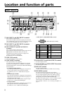
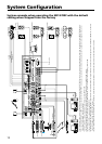
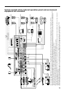
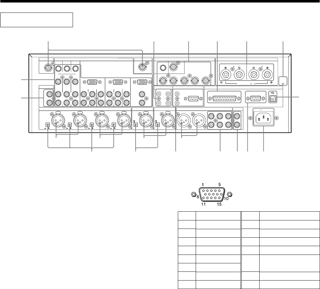
Rear panel
LINE4 INPUT
LINE3 IN
AC IN
+48V +48V +48V +48V
(+48V) (+48V)
1234 21
3
4
5
6
L
R
FRONT
RS-232C
COMPONENT/RGB
B
7
8
1
2
MIC INPUT LINE OUTPUT
ACD E F
VIDEO
ANT IN a ANT IN b OUTPUT
R/R-Y
VIDEO
SPEAKERS
REC OUT
REMOTE
PARALLEL
S VIDEO
S VIDEO
CONTROL S
IN
OUT
PROJECTOR CONTROL
MIC5/LINE1 IN
OUTPUT
IMPEDANCE USE
4-16
70V LINE
G/Y B/B-Y
SYNC/HD
VD
L
R
L
L
R
REAR
CENTER
WOOFER
FRONT
L
R
REAR
CENTER
WOOFER
L
R
ON OFF ON OFF ON OFF ON OFF
MIC
LINE
MIC
LINE
1
2
3
4
CH-1CH-2
IMPEDANCE USE
4-16
IMPEDANCE USE 32 -10k
DC
9V OUT
35mA MAX
DC
9V OUT
35mA MAX
R
CIRCUIT
BREAKER
PUSH RESET
MIC6/LINE2 IN
CONTROL S
RS-232C
qh qa 0 qd 9 w;
qg
1236
qk ql qs 7 8 qf qj
5
4
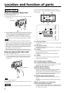
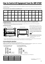
<LINE4 INPUT COMPONENT/RGB terminal>
(HD D-sub 15-pin, female)
Pin No.
1
2
3
4
5
6
7
8
Function
Video input R/R-Y
Video input G/Y
Video input B/B-Y
GND
N.C
GND
GND
GND
Pin No.
9
10
11
12
13
14
15
Function
N.C
GND
N.C
N.C
Composite sync signal/
horizontal sync signal, SYNC/HD
Vertical sync signal VD
N.C
Location and function of parts