


13
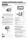
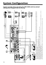
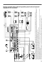
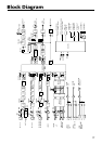
System example when external operation panel and environment
equipment are connected
LINE4 INPUT
LINE3 IN
AC IN
+48V
+48V
+48V
+48V
1234
21
3
4
5
6
L
R
FRONT
RS-232C
COMPONENT/RGB
B
7
8
1
2
MIC INPUT
LINE OUTPUT
ACD E F
VIDEO
ANT IN a
ANT IN b OUTPUT
R/R-Y
VIDEO
SPEAKERS
REC OUT
REMOTE
PARALLEL
S VIDEO
S VIDEO
CONTROL S
IN
OUT
PROJECTOR CONTROL
MIC5/LINE1 IN
OUTPUT
IMPEDANCE USE
4-16
70V LINE
G/Y B/B-Y
SYNC/HD
VD
L
R
L
L
R
REAR
CENTER
WOOFER
FRONT
L
R
REAR
CENTER
WOOFER
L
R
ON
OFF ON
OFF ON
OFF ON
OFF
MIC
LINE
MIC
LINE
1
2
3
4
CH-1CH-2
IMPEDANCE USE
4-16
IMPEDANCE USE 32
-10k
DC
9V OUT
35mA MAX
DC
9V OUT
35mA MAX
R
CIRCUIT
BREAKER
PUSH RESET
MIC6/LINE2 IN
CONTROL S
RS-232C
(+48V)(+48V)
I/F
BOX
I/F
BOX
Component
5.1 channel surround
RGB
AUDIO
RGB
AUDIO
PC 1
PC 2
To power outlet
Center speaker (C) Sub woofer (SW)
Power amplifier
Power amplifier
Power amplifier
Ceiling speaker
Surround speaker (LS) Surround speaker (RS)
USB
USER CONTROL PANEL
External operation panel
To power outlet
LCD data projector
Front speaker (L) Front speaker (R)
R/G/B/HD/VD Y/R-Y/B-Y
VIDEO
S VIDEO
RS-232C or CONTROL S
RS-232C
Screen Curtain
Illumination
Operation terminal
External system controller
I/F
BOX
IR
transmitter
MD recorder
VHS VCR
DV VCR
CD player
DVD player
• You can control the SRP-X700P from a remote location by one of the three methods (either from the User Control Panel or from the external operation panel or from external system controller.)
• You can control the SRP-X700P and the equipment connected to the SRP-X700P by sending command from external system controller to the SRP-X700P. (The system controller software is separately necessary.)
• If you use a projector that is controlled through the CONTROL S terminal, the RGB signal equipment and the component signal equ
ipment cannot be mix
ed in the system connection. The component signal
output equipment such as DVD should use the 4A to 4C LINE 4 INPUT terminals connecting the video or S video signal.
• The system configuration shown above uses the two unit of the UHF synthesizer tuner unit WRU-806B (option).
• If you want to use an electret condenser microphone for MIC3 and MIC4, set the +48 V button of the corresponding channel to ON.
• Install the IR transmitter VM-50 in the SRP-X700P or in the location inside a rack that allows its receptor block to receive the remote control signal. For the installation of the VM-50, see “How to Control AV
Equipment from the SRP-X700P
” on page 11.
• If you want to control the environment equipment such as screen, curtain and illuminations from the REMOTE PARALLEL output terminal, use the optional interface box (I/F box).
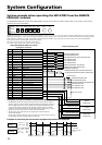
• For the external operation panel and interface box (I/F Box), see “System example when operating the SRP-X700P from the REMOTE PARALLEL terminal” on page 14.