


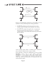
Each input channel and the three main outputs have an Insert
‘A’ gauge jack socket, which is a break point in the signal
path. It allows the signal to be taken out of the mixer,
through an external piece of equipment and then back into the
mixer directly after its original exit point. The Insert point is
normally bypassed by the ‘A’ gauge jack socket contacts, and
is only brought into operation when a plug is inserted.
Typical uses would include Effects Processors, Limiters,
additional Equalisers or Delay units. In addition, each
channel has a Direct output which may also be used to feed
external equipment.
The terms PRE and POST are often used in the context of
Inserts, Equalisers and Auxiliary Sends, and describe whether
that facility is placed before (Pre) or after (Post) another
particular section. This is explained further in the detailed
description of facilities.
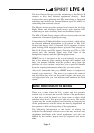
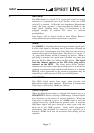
A mixer is often judged, amongst other factors, by the amount
of Headroom available. This is a measure of the reserve
available to cope with sudden peaks in the input signal,
without distortion caused by Clipping, when the signal
becomes so high that it would exceed the power supply rail
voltages and is as a result limited. This commonly occurs
where gain settings are incorrectly set or where sources are
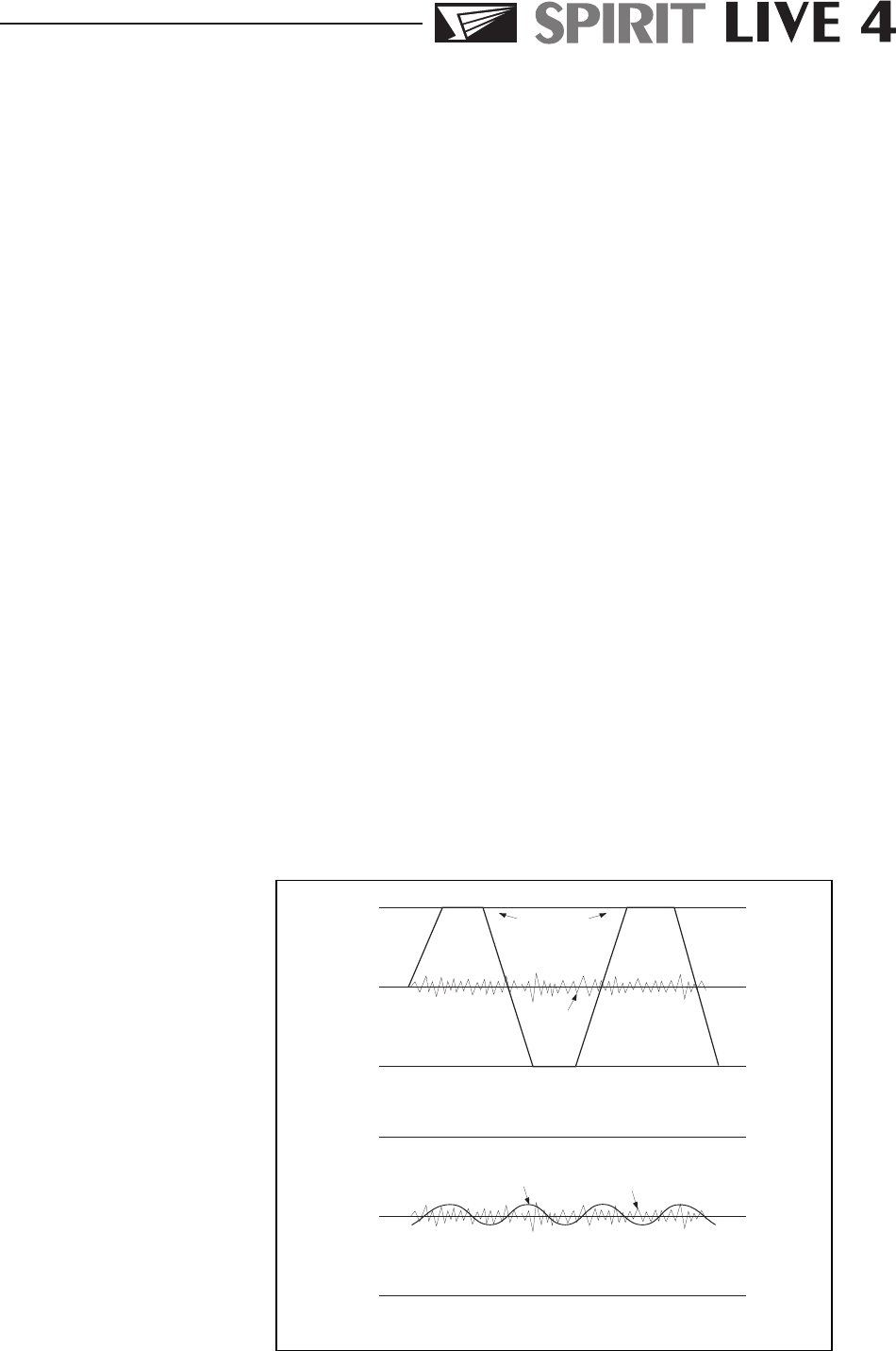
improperly matched to the mixer input. If the source signal is
too high, clipping and distortion results. If the signal is too
low it becomes masked by the background noise which is
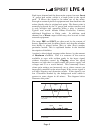
present to some degree in all mixers. The diagram below
illustrates this point.
If the signal level is too low it may be masked
by the noise.
Signal
Noise
If the signal level is too high, clipping distortion
may occur.
Clipped
Signal
Noise
Pa g e 5