


Nucleus User Guide Page 31
C
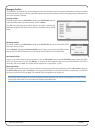
onfiguring Continuous Controller Layers
W
hen a Continuous Controller Profile is assigned to a Nucleus DAW Layer, Continuous Controller (‘CC’) messages are sent on
c
hannel 1 of the first MIDI send port assigned to that Layer. These messages can be used to control software instruments
w
ithin the current DAW by using the DAW’s MIDI ‘learn’ mode to attach messages to instrument plug-in parameters.
Alternatively, an external hardware MIDI device can be controlled by assigning it to the output of a MIDI track in the DAW
whose input is receiving the CC control data from a Nucleus DAW Layer. Logic provides a further mechanism to integrate
external MIDI hardware via the capabilities of the Logic Environment.
CC Layers are unidirectional (one way). No CC data is returned from the device to Nucleus and all front panel positional
indication is derived locally, not from the device itself.
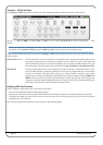
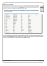
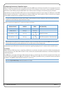
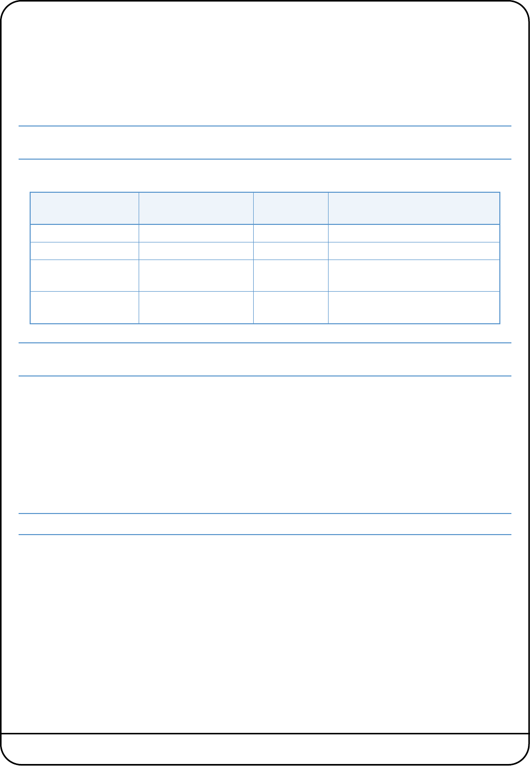
Nucleus controls are mapped to CC numbers and values as follows:
Note that the V-Pots function as absolute controllers, not as incremental devices and that the SEL and V-Sel switches
emulate latched switches sending appropriate ‘on’ and ‘off’ values as they change state.
Please refer to your MIDI device’s manual for instructions regarding mapping these CC numbers within the MIDI device.
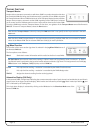
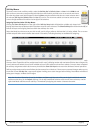
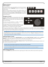
CC Displays
When a Nucleus DAW Layer that is controlling a MIDI device is selected, the bottom row of the scribble strip displays the
V-Pot CC Number or User label. When a fader or V-Pot is moved, the associated label switches to a momentary display of the
value being altered.
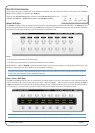
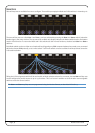
The FLIP switch to the right of the left scribble display (see Page 35) interchanges the controllers assigned to the Faders and
V-Pots as well as the DAW channel SEL and V-Sel switches. This makes it possible to have 32 controller channels available to
the faders, using FLIP to switch between channels 0-15 and 16-31.
Note that Flip Scribble Strips cannot be used on a CC layer.
Nucleus Control
Continuous Controller
Number Value ‘On’ State Tally
Faders 1 to 16 0 to 15 0 to 127 -
V-Pots 1 to 16 16 to 31 0 to 127 -
SEL switches 1 to 16 64 to 79
0 = ‘off’
127 = ‘on’
Switch illuminates
V-Sel switches 1 to 16 80 to 95
0 = ‘off’
127 = ‘on’
Red LED beneath the V-Pot illuminates