


Nucleus User Guide Page 3
1. Nucleus Overview
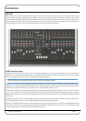
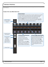
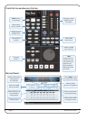
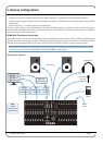
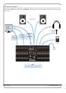
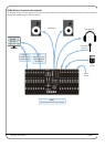
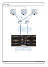
The diagrams below and overleaf provide an overview of the Nucleus control surface along with the main DAW screen of the
Nucleus Remote.
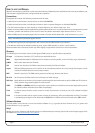
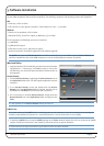
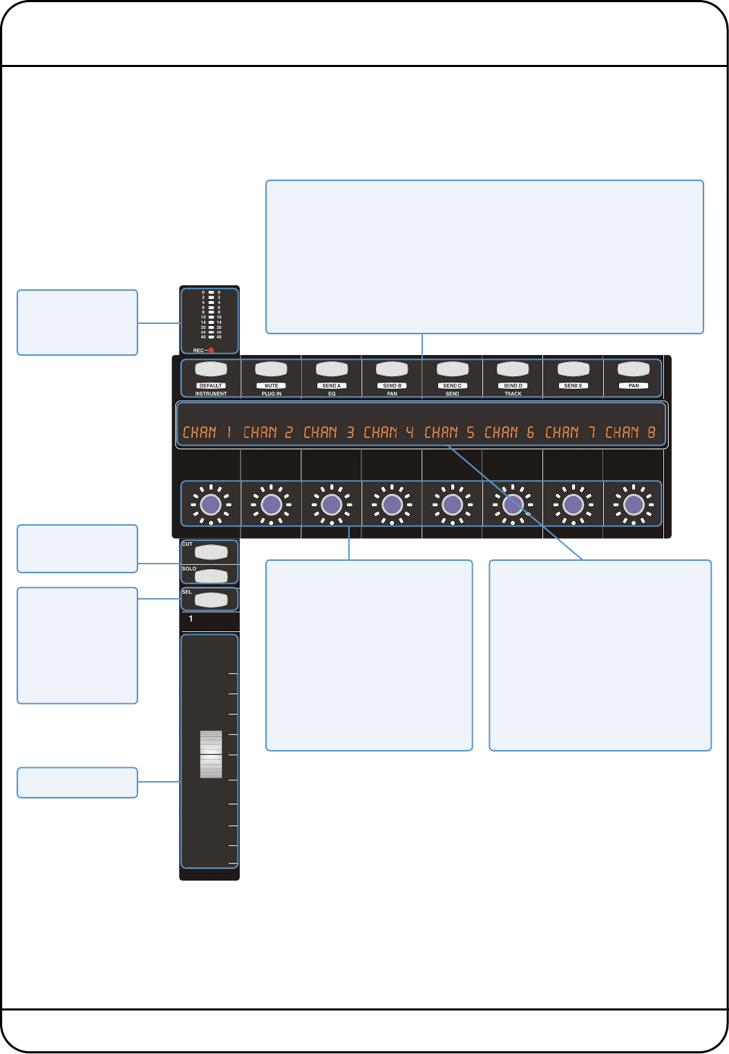
CHANNEL STRIP AND MODE SWITCHES
Channel meter
and record status
indicator
Mode Switches
The Mode switches are not part of the channel in which they are located.
In normal operation, they select V-Pot modes. By default only Mode
switches 1-8 are assigned. Note that the V-Pot modes are printed
beneath the switches, and not shown in the digital display.
When the USER switches in the centre section are pressed, the Mode
and V-Sel switches in channels 9-16 become soft switches (Soft Keys)
which can be configured using the Nucleus Remote.
2-Row ‘Scribble Strip’ Display
In normal operation, the top row
displays the channel name and the
bottom row the V-Pot function.
When the centre section USER
switches are selected, the digital
display on channels 9-16 shows the
soft key assignments for each
corresponding Mode and V-Sel
switch.
V-Pots and V-Sel Switches
- Turn for the V-Pot
- Press for the V-Sel switch
Functions are defined by the
host application, or by pressing
a Mode switch.
When the centre section USER
switches are selected, Mode and
V-Sel switches in channels 9-16
become additional soft switches.
Channel Cut and
Solo switches
Channel Select
switch.
Also used for
track arming,
automation and
plug-in control.
Channel Fader