


At your first introduction to the Duality console, you will immediately see that the channel strip controls are
presented in reassuringly familiar manner. The following pages describe each control in detail, with brief
coverage of the routing possibilities. See the start of this section for more on signal routing.
In the following descriptions, the connectors referred to are on the rear of each channel module,
unless stated otherwise.
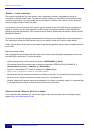
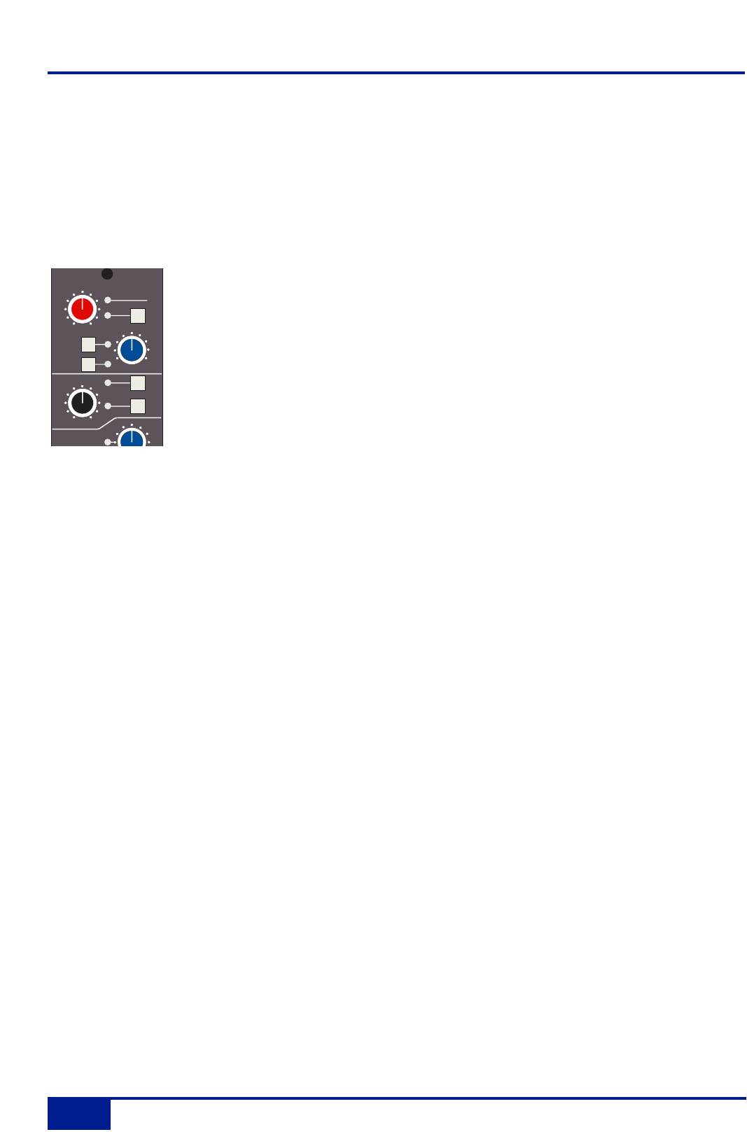
Channel Input Section
This provides two inputs, one dedicated as a line level DAW return (D-connector), the
other (XLR connector), is intended as a mic input but may be used for both mic or line
inputs. Normally the Mic Input feeds the variable gain INPUT amplifier, and the DAW
return feeds a unity gain line amp. However a centrally controlled INPUT FLIP function
reverses the input routing so that the DAW return can be processed by the variable gain
amplifier stage without the necessity for external patching.
The variable gain amplifier features two completely independent preamp stages. Both have electronically
balanced inputs with very different but complementary sonic qualities. The default preamp uses SSL's
acclaimed Super Analogue circuitry to provide an extremely low noise, extended bandwidth front end with the
minimum of signal colouration. Pressing the DRV IN button routes the input signal to a completely different
preamp featuring the SSL-developed VHD™ (Variable Harmonic Drive) circuitry. VHD emulates the
characteristics of a classic valve front end but with the option to tailor the harmonic mix when the preamp is
overdriven by adjusting the DRIVE pot. In conjunction with the 20dB PAD and Hi-Z input impedance option,
VHD can provide subtle valve style warmth to a mic signal or aggressive tonal shaping to existing DAW tracks.
However, be aware that, due to differences in the mic amp topology, exact matching of gains is not possible.
Note that many of the signal routing functions on a channel strip are also available
on the central routing panel, and some are only available on the central routing panel
The post input stage CH (channel) control provides final ±20dB gain trim (for reducing the level when the input
section is being abused for creative reasons) and polarity inversion (Ø), for the centrally selected channel
source. Available input options are the output of the mic input preamp (MIC), the balanced line level DAW
return (LINE), or the channel’s associated track bus for patch free subgroups (BUS). In the latter case, the
channel input is replaced by the output of one of the 24 Track Mix busses where Bus N feeds the input of
Channel N, N+24, N+48 etc.
FILT to INP locks the high and low pass filters to the channel source. +48V phantom power for mic inputs is
selected on the central routing panel.
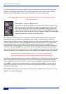
COMPRESSOR
INPUT
CH
dB
-20
+20
48V
dB
+15
+75
PAD
2nd
3rd
FILT
to
INP
Ø
HI-Z
DRV
IN
0
DRIVE
Console Operator’s Guide
2-4
Duality Operator’s Manual