


Central Dynamics Control
The centre section master routing panel replicates the dynamics POST EQ function for sweet spot control and
multiple channel operation using the SELECT/TO range keys.
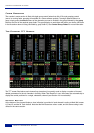
Dynamics Section Metering
The TFT screen above each bay of six channel strips is used to display a wide variety of relevant information.
In its default Channel mode, as well as channel output metering (see later) a display of dynamics section gain
processing is shown, in the form of two columns of indicators – yellow and red for the compressor, green for
the gate/expander. See Channel Metering for more information.
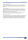
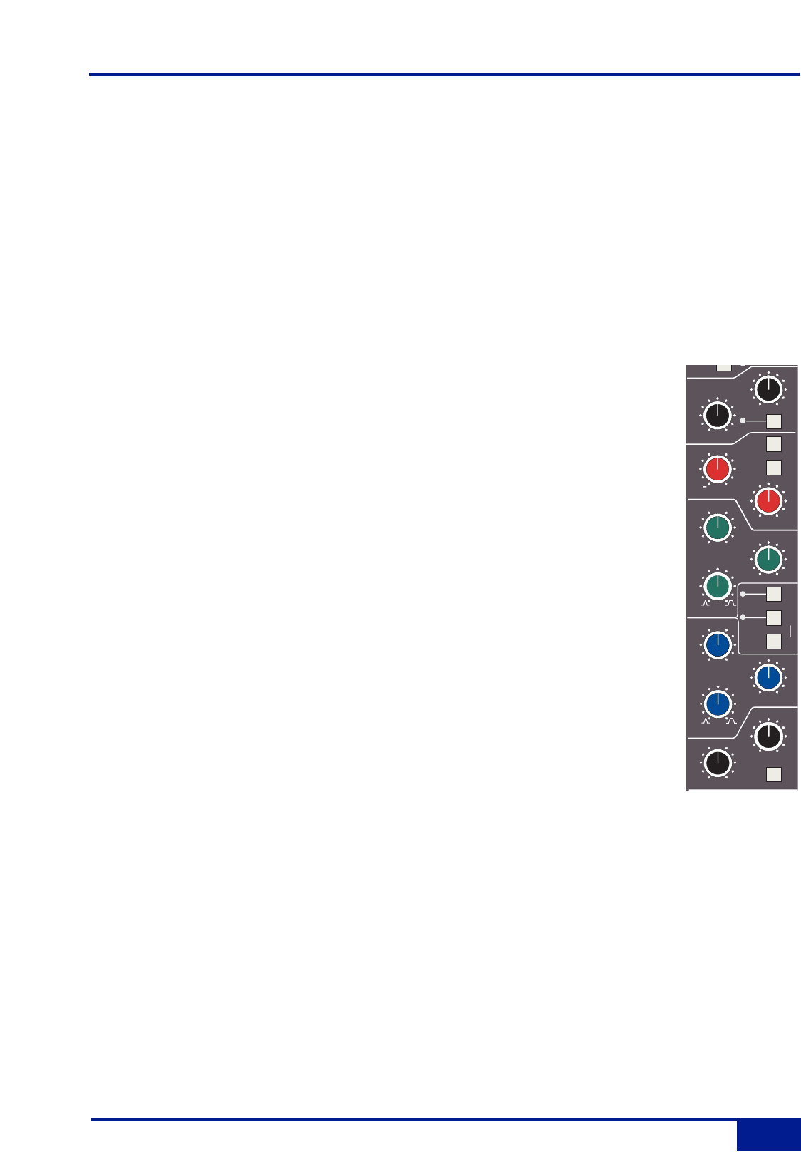
Filters
These comprise a 3rd Order 18dB/Octave high pass filter (HF) and a 2nd Order
12dB/Octave low pass filter (LF). Each filter is out of circuit when the control is fully
anticlockwise. When the filter is in circuit, the FILTER box on the channel TFT display is
highlighted.
Normally, the filters follow the EQ section in the signal chain but the FILT to INP button
in the input section of the channel strip places the filters directly after the channel input.
This function is also available on the central routing panel. Pressing TO S/ch routes the
filter section to the dynamics sidechain.
Signal processing order is graphically displayed on the channel TFT screen
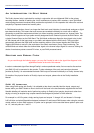
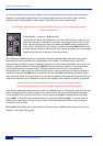
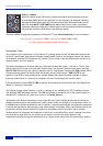
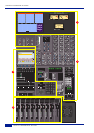
Equaliser
This is a four band parametric equaliser based on SSL’s classic 'Black Knob' EQ, which
was developed for the original SL4000E series console. Selecting the G-EQ button
introduces steeper shelving curves with a controlled amount of undershoot at the
turnover frequency, together with the classic gain/bandwidth interaction for the mid band
sections that was a key characteristic of the original G-Series EQ.
The individual bands function as follows: HF high frequency shelving equaliser
switchable to fixed Q parametric (BELL); HMF high frequency parametric mid band
equaliser; LMF low frequency parametric mid band equaliser; LF low frequency shelving
equaliser switchable to fixed Q parametric (BELL). The EQ IN button (located next to the
insert buttons) routes the channel signal through the EQ and filter section. When in
circuit, the EQ box on the channel TFT display is highlighted. See also Central Routing
Control.
LMF
dB
Q
KHz
Hz
Q
+
.2
2.0
40
600
KHz
HMF
dB
+
0
KHz
.6
7
LF
BELL
BEL
L
dB
0
LF
+
0
HF
dB
+
0
Hz
500
20
EQ
IN
POS
T
INS
IN
HF
OUT
3
G-E
Q
TO
S/Ch
IN
60
15
0
220
400
.3
.
6
1.
0
kHZ
-
-
-
1
2
3
5
30
9
6
4
30
60
100
300
FILTERS
1.5
22
15
10
5
2
Filters and EQ
2-7
Duality Operator’s Manual