


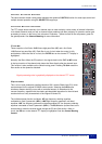
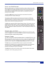
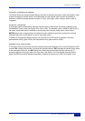
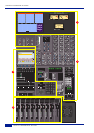
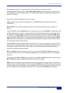

Channel Processing Order
The section above the routing indicators displays the order of channel processing for both signal paths in each
channel (including the channel inputs, the channel fader and the channel output) as well as providing an
indication of which processing element is actually in circuit. Once again, colour coding is used for ease of
recognition.
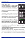
Channel Metering
A single peak meter indicates either analogue channel signals or DAW levels, according to selection of the
Console/DAW ‘Focus’ button (see Section 3 for more on this). The standard scale is +24dB for 0dBFS (top of
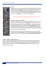
the scale). A peak hold option is available for channel and centre section meters via the centre section
METERS setup menu. A legend below the Dynamics section indicators (see below) confirms the currently
selected meter point for that channel, as set on the central routing.
In addition to the expected channel metering, two columns of five ‘LEDs’ give an indication of channel
gate/expander activity (green ‘LEDs’) and compressor activity (yellow and red ‘LEDs’).
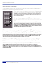
DAW Status Indicators
To the right of each channel meter are three indicators that provide feedback of the current DAW status of that
channel. SEL confirms that channel is currently the ‘selected channel’. REC indicates the Record Ready status
of the associated DAW track, and EDIT shows if the DAW channel associated with that channel strip is
currently assigned to the plug-in editor (Pro Tools only). See Section 3 for more details. Note that Record
Ready and Edit status will be indicated regardless of whether the console is in ‘DAW Focus Mode’ or not.
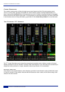
Channel TFT Screen
2-13
Duality Operator’s Manual