8 Input Patch / Output Patch operations
78 PM5D/PM5D-RH V2 / DSP5D Owner’s Manual Operating section
Here we will explain how to make insert connections,
using an example in which an external device connected to
an AD/DA card in a slot is inserted into an input channel.
However, the procedure is the same when inserting into an
output channel, the only difference being that you will be
working in a screen for output channels.
1
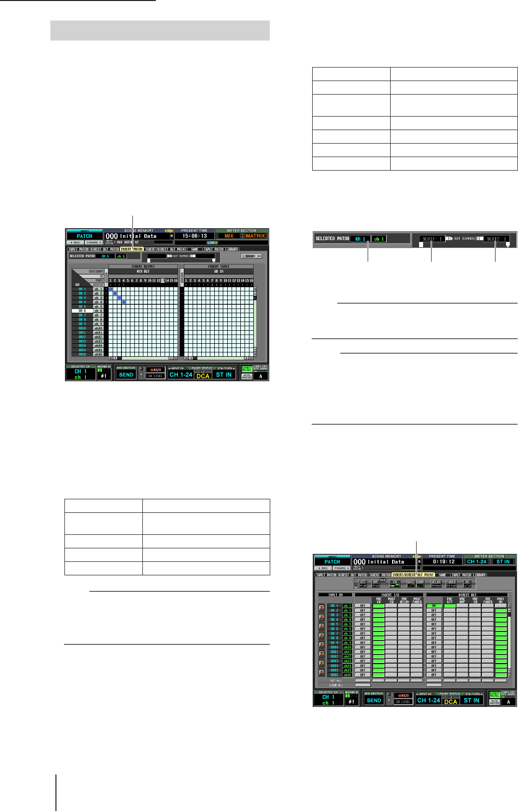
In the DISPLAY ACCESS section, press the
INPUT [PATCH] key several times to access the
INSERT PATCH screen (INPUT PATCH func-
tion) shown below.
In the left side of this screen you can select an output
port to use as insert-out, and in the right side of the
screen you can select an input port to use as insert-in.
If you want to insert into an output channel, press the
OUTPUT [PATCH] key several times to access the
OUTPUT PATCH function INSERT PATCH screen.
2
In the left side of the screen, click the grid at
which the output port connected to your
external device intersects the desired channel.
The procedure is the same as in the INPUT PATCH
screen or OUTPUT PATCH screen. You can select the
following output ports.
Hint
If you select GEQ IN at the left side of the screen, the identi-
cally-numbered GEQ OUT will be automatically selected at
the right side of the screen, inserting the correspondingly-
numbered GEQ module into that channel. (For details on
using the graphic EQ
➥
p.118)
3
In the right side of the screen, click the grid at
which the input port connected to your exter-
nal device intersects the desired channel.
You can select the following input ports.
The SELECTED PATCH area shows the channel corre-
sponding to the grid at which the cursor is located. To
the right of this are shown the input/output ports
patched to insert-out/insert-in for this channel.
Hint
To move the cursor rapidly between the grids in the left and
right sides of the screen, you can hold down the [SHIFT] key
and press the CURSOR [
√
]/[
®
] keys.
Note
With the steps you have taken so far, the external device has
been patched to the insert-out/insert-in of the selected chan-
nel. However, please note that the insert connection is not
actually enabled until you turn on the INSERT I/O ON/OFF
button in the INSERT/DIRECT OUT screen as described
below. As an exception to this, the INSERT I/O ON/OFF but-
ton is automatically turned on if you patch a GEQ.
4
Press the INPUT [PATCH] key several times to
access the INSERT/DIRECT OUT POINT screen
(INPUT PATCH function) shown below.
In the INSERT/DIRECT OUT POINT screen (INPUT
PATCH function) you can switch insert on/off for each
input channel. In this screen you can also select the
insert I/O point (the location at which the external
device will be inserted).
If you want to insert into an output channel, press the
OUTPUT [PATCH] key several times to access the
OUTPUT PATCH function INSERT PATCH screen.
MIX OUT 1–24 MIX OUT jacks 1–24
SLOT OUT 1–4
Output channels of an I/O card
installed in slots 1–4
FX IN 1–8 L/R inputs of internal effects 1–8
GEQ IN 1–12 Inputs of GEQ modules 1–12
2TR OUT 1–3 2TR OUT DIGITAL jacks 1–3 (L/R)
Patching the insert-out and insert-in
INSERT PATCH
AD IN 1–48 INPUT jacks 1–48
AD ST IN 1–4 ST IN jacks 1–4 (L/R)
SLOT IN 1–4
Input channels of an I/O card
installed in slots 1–4
FX OUT 1–8 Outputs (L/R) of internal effects 1–8
GEQ OUT 1–12 Outputs of GEQ modules 1–12
2TR IN D1–D3 2TR IN DIGITAL jacks 1–3 (L/R)
2TR IN A1/A2 2TR IN ANALOG jacks 1/2 (L/R)
Channel at which
the cursor is located
Port patched to
insert-out
Port patched to
insert-in
INSERT/DIRECT OUT POINT
