


English
Controls and Functions
Owner’s Manual
10
0
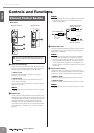
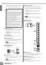
COMP Control/Indicator
Adjusts the amount of compression applied to the chan-
nel. As the COMP knob is turned to the right the com-
pression ratio increases while the output gain is
automatically adjusted accordingly. The result is
smoother, more even dynamics because louder signals
are attenuated while the overall level is boosted. The
COMP indicator will light when the compressor oper-
ates.
NOTE
·Avoid setting the compression too high, as the higher
average output level that results may lead to feedback.
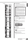
A EQ (Equalizer): HIGH, HI-MID, LO-MID, LOW
This is a four-band equalizer, providing adjustments for
four frequency bands (HIGH, HI-MID, LO-MID, LOW).
Setting the gain control to the “▼” position produces a
flat response in the corresponding band. Turning the
gain control to the right boosts the corresponding fre-
quency band, while turning to the left attenuates the
band. The HI-MID and LO-MID bands of monaural
channels provide a frequency control that lets you
adjust the center frequency.
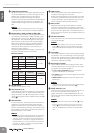
The following table shows the EQ type, frequency, and
maximum cut/boost for each of the bands.
Monaural channel
Stereo channel
B EQ ON Switch
Switches the equalizer on or off.
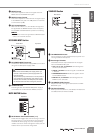
C AUX Controls (1–8)
These adjust the level of the signals sent from the input
channel to AUX buses 1–8. These knobs should gener-
ally be set close to the “▼” (nominal) position. The sig-
nal adjusted by these controls is determined by the PRE
switch (D).
D PRE Switches
For each two buses, these switches select whether the
signal sent to the AUX buses will be taken after the
equalizer and before the channel fader (pre-fader), or
after the channel fader (post-fader). If this switch is ON,
the pre-fader signal is sent to the AUX bus, and will not
be affected by the channel fader.
NOTE
· If necessary, the pre-fader signal sent to the AUX buses
can be changed to the signal before the equalizer by
changing an internal jumper. A fee will be charged for
this modification. In this case, the signal will be sent to
the AUX buses even if the input channel’s ON switch is
turned off. For details, contact to your Yamaha dealer
listed at the end of this manual.
E PAN Control
This control determines the stereo positioning of the
monaural channel signal on the buses.
Rotate the knob clockwise to pan the signal to the odd
channels of the GROUP buses and the ST L bus, and
counter-clockwise to pan the signal to the even chan-
nels of the GROUP buses and the ST R bus.
F BAL Control
Adjusts the left and right volume balance of stereo
channels. The signal input to the INPUT L jack will be
sent to the odd channels of the GROUP buses or to the
ST L bus, and the signal input to the INPUT R jack will
be sent to the even channels of the GROUP buses or to
the ST R bus.
G ON Switch/Indicator
When this switch is on, that channel will be enabled and
the indicator will light.
NOTE
· Even if the ON switch is off, you can turn on the PFL
switch (K) and monitor the signal before the channel
fader via the MONITOR OUT jacks and the PHONES
jack.
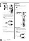
H Input Meter
Three LEDs indicate the input channel signal level after
the equalizer. The “-20” LED will light if the input signal
level reaches -20 dB, and the “0” LED will light at nomi-
nal level. The PEAK LED will light red when the input sig-
nal reaches 3 dB before clipping.
I Bus Assign Switches
These switches determine the bus(es) to which each
channel’s signal is sent. Turning a switch on will output
the signal to the corresponding bus.
• 1-2, 3-4, 5-6, 7-8 switches: Assign the channel’s
signal to the GROUP 1/2–7/8 buses.
• ST switch: Assigns the channel’s signal to the Stereo
L and R buses.
• MONO switch: Assigns the channel’s signal to the
MONO bus.
NOTE
· If you want the signal to be output to the corresponding
bus(es), turn on the channel ON switch (G).
J MUTE Switches (1–4)
These assign the channel’s mute on/off to switches 1–4.
If you turn on the MUTE master switches (1–4)
(page 15) located in the MUTE MASTER section, the
input channels whose corresponding MUTE switch is on
will be muted.
NOTE
·When a channel is muted, the ON indicator (G) will go
dark.
· Even if a channel is muted, you can turn on the PFL
switch (K) and monitor the signal before the channel
fader via the MONITOR OUT jacks and the PHONES
jack.
Band Type Frequency
Maximum
Cut/Boost
HIGH Shelving 10 kHz
±15 dB
HI-MID Peaking 400 Hz – 8 kHz
LO-MID Peaking 80 Hz – 1.6 kHz
LOW Shelving 100 Hz
Band Type Frequency
Maximum
Cut/Boost
HIGH Shelving 10 kHz
±15 dB
HI-MID Peaking 3 kHz
LO-MID Peaking 800 Hz
LOW Shelving 100 Hz