


English
Controls and Functions
Owner’s Manual
14
the data. If the computer or the instrument freezes,
restart the application software or the computer OS, or
turn the power to the instrument off then on again.
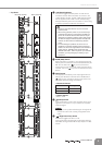
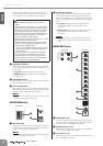
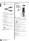
3 Bus Assign Switches
These switches determine the bus(es) to which the sig-
nal received from the 2TR IN jacks and the USB con-
nector is sent.
• ST switch: Sends the signal to the ST L/R bus.
• MONO switch: Sends the mixed L and R signal to
the MONO bus.
4 2TR IN/USB Control
Adjusts the level of the signal received from the 2TR IN
jacks and the USB connector.
5 PFL Switch/Indicator
When the PFL switch is on, the indicator will light and the
signal before the 2TR IN/USB control is output to the MON-
ITOR OUT and PHONES jacks for monitoring.
NOTE
·When you turn on the PFL switch, the PFL indicator of the
MONITOR section (page 18) will light.
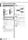
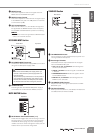
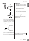
REC OUT/USB Section
1 REC OUT Jacks
These RCA pin jacks can be connected to an external
recorder such as an MD recorder in order to record the
signal of the ST L/R bus or MONO bus.
NOTE
· The STEREO OUT master fader and MONO fader has no
affect on the signal via these jacks.
2 Bus Assign Switches
These switches determine the signal sent to the REC
OUT jacks and USB connector. If you’re sending the
signal of the MONO bus, the same signal will be output
to the L and R of the REC OUT jacks and the USB con-
nector.
• ST switch: The signal of the ST L/R bus will be
output from the REC OUT jacks and the USB
connector.
• MONO switch: The signal of the MONO bus will be
output from the REC OUT jacks and the USB
connector.
NOTE
· If both the ST switch and the MONO switch are on, the
mixed signals of the ST L/R bus and MONO bus will be
output.
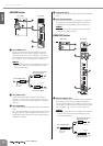
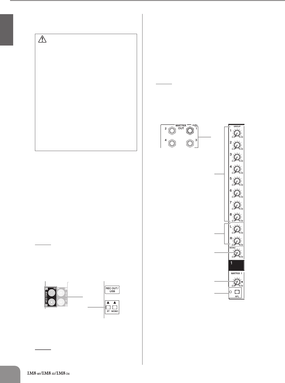
MATRIX OUT Section
1
MATRIX OUT Jack
This is an impedance balanced (page 19) TRS phone-
jack type output. This jack outputs the signal adjusted
by the controls in the MATRIX OUT section.
2 GROUP Controls (1–8)
These adjust the level of the signals sent from GROUP
OUT 1–8 to the MATRIX OUT jacks.
3 ST Controls (L, R)
These adjust the level of the signals sent from ST OUT L/
R to the MATRIX OUT jacks.
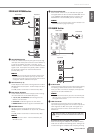
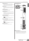
• Use an AB type USB cable of less than about 3
meters.
•To prevent loud pops and noises, turn on the power to
your equipment in the following order; first the audio
sources, then the PW8, and finally the power amplifi-
ers. Reverse this order when turning the power off.
• Before connecting the computer to the USB connector,
exit from any power-saving mode of the computer
(such as suspended, sleep, standby).
• Before turning on the power to the instrument, connect
the computer to the USB connector.
•Execute the following before turning the power to the
instrument on/off or plugging/unplugging the USB
cable to/from the USB connector.
- Quit any open application software on the computer.
-Make sure that data is not being transmitted from
the instrument.
•While the computer is connected to the instrument,
you should wait for six seconds or more between
these operations: (1) when turning the power of the
instrument off then on again, or (2) when alternately
connecting/disconnecting the USB cable.
1
2
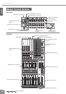
Rear Panel Top Panel
1
2
3
4
5
6
Rear Panel Top Panel