


English
Controls and Functions
Owner’s Manual
15
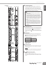
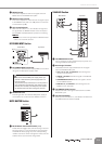
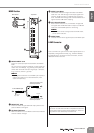
4 MONO Control
This control adjusts the level of the signal sent from
MONO OUT to the MATRIX OUT jacks.
5 MATRIX master Control
This control adjusts the overall level of the signal output
to the MATRIX OUT jacks. The “▼” position of the knob
is nominal level (0 dB).
6 AFL Switch/Indicator
When the AFL switch is on, the indicator will light and
the signal after the MATRIX master control is output to
the PHONES and MONITOR OUT jacks for monitoring.
NOTE
· If you want to monitor the signal after the MATRIX master
control, turn off all PFL switches.
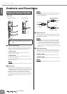
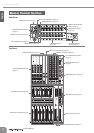
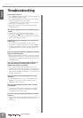
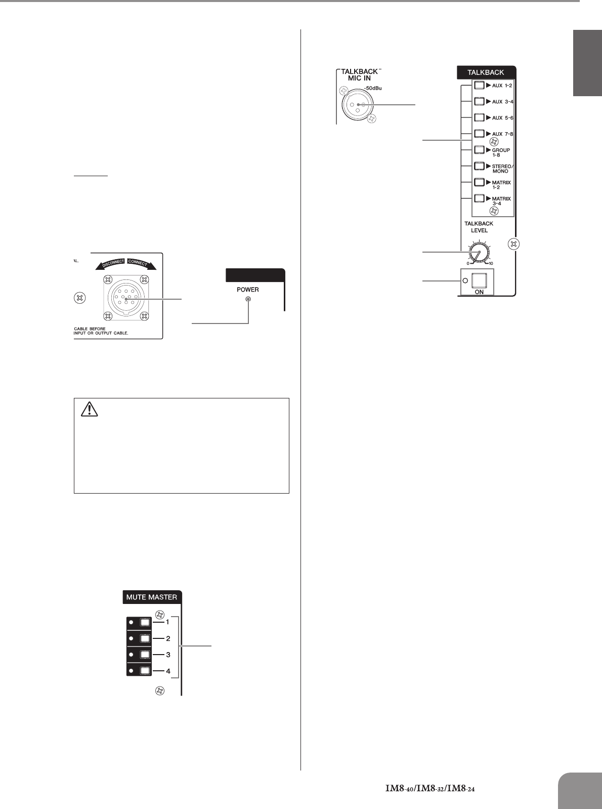
DC POWER INPUT Section
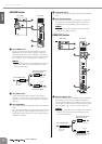
1
DC POWER INPUT Connector
Connects the Yamaha Power Supply PW8 to the console
using the included power supply cable.
2 POWER Indicator
This will light when the Yamaha PW8 power supply is
connected to the console and the PW8 is turned on.
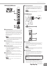
MUTE MASTER Section
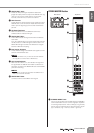
1
MUTE Master Switches/Indicators (1–4)
These switches toggle input channel muting on and off.
Turning a switch (1–4) on will mute the input channels
whose MUTE switch (page 10) of the corresponding
number is turned on. When the signal is muted, the ON
indicator of the input channels will go dark.
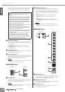
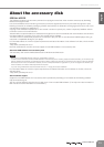
TALKBACK Section
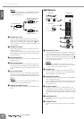
1
TALKBACK MIC IN Jack
This is an XLR-3-31 type unbalanced input jack for con-
necting a talkback microphone.
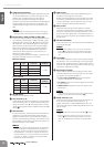
2 Bus Assign Switches
These determine the output destination of the signal
from the TALKBACK MIC jack.
• AUX 1-2, 3-4, 5-6, 7-8 switches: Send the signal to
the AUX 1/2–7/8 buses.
• GROUP 1-8 switch: Sends the signal to the GROUP
1–8 buses.
• STEREO/MONO switch: Sends the signal to the ST
L/R and MONO buses.
• MATRIX 1-2, 3-4 switches: Send the signal to the
MATRIX 1/2 or 3/4 buses.
3 TALKBACK LEVEL Control
Adjusts the level of the signal received from the TALK-
BACK MIC jack.
4 ON Switch/Indicator
When you turn this switch on, the indicator will flash and
the talkback function will be enabled.
•Turn off the Yamaha PW8 power supply before you
connect or disconnect the power supply cable to or
from the console.
•To prevent loud pops and noises, turn on the power to
your equipment in the following order; first the audio
sources, then the PW8, and finally the power amplifi-
ers. Reverse this order when turning the power off.
N
PUT
1
2
Rear Panel Top Panel
1
Top Panel
1
2
3
4
Rear Panel Top Panel