


English
Controls and Functions
Owner’s Manual
17
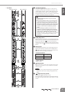
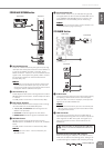
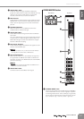
2 GROUP OUT Jacks
These are TRS phone type impedance-balanced
(page 19) output jacks that output the GROUP OUT sig-
nals. You can connect these jacks to a multi-track
recorder, external mixer, or other such device.
3 PAN Controls
These adjust the stereo position of the signals sent from
GROUP OUT to the ST L/R bus. Rotate the knob clock-
wise to pan the signal right, and counter-clockwise to
pan left.
4 ON Switch/Indicator
When this switch is on, that GROUP OUT will be
enabled and the indicator will light.
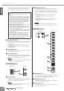
5 GROUP OUT Meter
Three LEDs indicate the signal level after the GROUP
OUT fader.
The “-20” LED will light if the output signal level reaches
-20 dB, and the “0” LED will light at nominal level. The
PEAK LED will light red when the GROUP OUT signal
reaches 3 dB before clipping.
6 Bus Assign Switches
These switches assign the GROUP OUT signal to the ST
L/R bus and the MONO bus.
NOTE
·Turn the ON switch on if you want to send the GROUP
OUT signal to the ST L/R bus or MONO bus.
7 AFL Switch/Indicator
When the AFL switch is on, the indicator will light and
the signal after the GROUP OUT fader but before the
ON switch is output to the MONITOR OUT and PHONES
jacks for monitoring.
NOTE
· If you want to monitor the signal after the GROUP OUT
fader, turn off all PFL switches.
8 GROUP OUT Fader
Controls the level of the GROUP OUT signal.
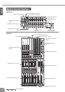
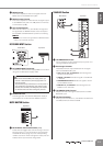
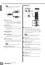
STEREO MASTER Section
1
STEREO INSERT Jack
This is an input/output jack located before the STEREO
OUT master fader. You can connect a graphic equalizer
or other signal processor. This is a TRS (tip, ring, sleeve)
phone jack that carries both the send and return signal
(tip = send/out; ring = return/in; sleeve = ground).
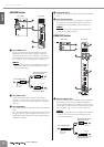
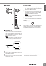
3
4
7
5
6
1
2
Rear Panel Top Panel