


English
Introduction
Owner’s Manual
6
Introduction
Thank you for your purchase of the Yamaha IM8 mixing console. Please read through this manual carefully
before beginning use, so that you will be able to take full advantage of your mixer’s superlative features and
enjoy trouble-free operation for years to come. After you’ve read the manual, keep it safe for future reference
when needed.
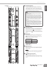
• Input channels
The console provides 40 monaural input channels (the
IM8-32 has 32 channels, and the IM8-24 has 24 channels)
that can accommodate mic through line-level devices, as
well as four stereo inputs that can accommodate line-level
devices.
• Compressors
A compressor is provided on every monaural channel.
Using just a single knob, you can compress the peaks of
the input signal from a source such as a microphone or
acoustic instrument (e.g., guitar), raising the overall vol-
ume without allowing the sound to distort.
•AUX SEND faders
Faders are provided on the AUX sends, allowing you to
use them not only for the main mix but also to create indi-
vidual mixes for monitoring.
• Owner’s Manual (this book)
•Power supply cable
• Cubase AI 4 DVD-ROM
• USB cable
Introduction .........................................6
Features................................................................................ 6
Accessories .......................................................................... 6
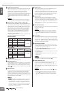
System Requirements........................................................... 7
Differences between the IM8-40/32/24 mixers ..................... 7
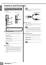
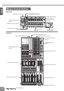
Controls and Functions .......................8
Channel Control Section....................................................... 8
Master Control Section ....................................................... 12
STEREO AUX RETURN Section.................................... 13
2TR IN/USB Section...................................................... 13
REC OUT/USB Section ................................................. 14
MATRIX OUT Section.................................................... 14
DC POWER INPUT Section........................................... 15
MUTE MASTER Section................................................ 15
TALKBACK Section ...................................................... 15
AUX SEND Section ....................................................... 16
GROUP OUT Section.................................................... 16
STEREO MASTER Section............................................ 17
MONITOR Section ........................................................ 18
MONO Section.............................................................. 19
LAMP Connector........................................................... 19
Troubleshooting.................................20
About the accessory disk..................21
Specifications..................................166
Electrical Specifications.................................................... 166
General Specifications...................................................... 167
Analog Input Specifications.............................................. 167
Analog Output Specifications........................................... 168
Digital Input/Output Specifications................................... 168
Jack List............................................................................ 169
Dimensional Diagram ....................................................... 170
Track Sheet .....................................172
Block Diagram and Level Diagram..174
Features
Accessories
Table of Contents