


English
Controls and Functions
Owner’s Manual
18
NOTE
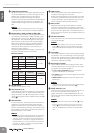
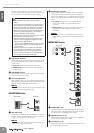
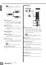
· Patching external devices via an INSERT jack requires a
special insert cable such as illustrated below (insert
cable sold separately).
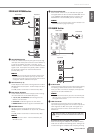
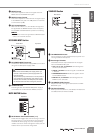
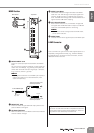
2 STEREO OUT Jacks
These are XLR-3-32 type balanced output jacks that
output the mixed stereo signal. They output the signal
adjusted by the STEREO OUT master faders (7). Con-
nect these jacks to the power amplifiers that drive your
main speakers.
3 STEREO Level Meter
These LEDs indicate the level of the signal sent to the
STEREO OUT jacks.
The “0” segment indicates the nominal output level. The
PEAK segment lights red when the output approaches
the clipping level.
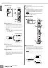
4 ON Switch/Indicator
When this switch is on, ST OUT will be enabled and the
indicator will light.
5 PFL Switch/Indicator
When the PFL switch is on, the indicator will light and
the signal before the STEREO OUT master fader is out-
put to the MONITOR OUT and PHONES jacks for moni-
toring.
6 AFL Switch/Indicator
When the AFL switch is on, the indicator will light and
the signal after the STEREO OUT master faders is out-
put to the PHONES and MONITOR OUT jacks for moni-
toring.
NOTE
· If you want to monitor the signal after the STEREO OUT
master faders, turn off all PFL switches.
7 STEREO OUT Master Faders
These adjust the signal level sent to the STEREO OUT
jacks.
MONITOR Section
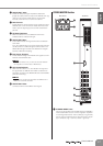
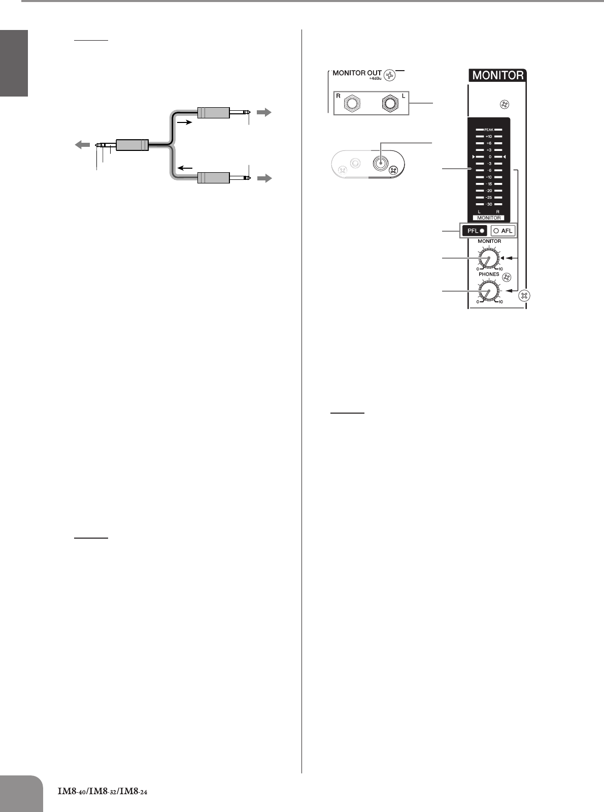
1
MONITOR OUT Jacks
These are impedance-balanced (page 19) TRS phone-
type output jacks that you can connect to your monitor
system. These jacks output the signal before or after the
faders for the various buses. The PFL/AFL indicator (4)
and the PFL and AFL indicators in each section indicate
which signal is being output.
NOTE
· If both a PFL switch and AFL switch are on, the PFL
switch will be enabled. If you want to monitor the signals
after the faders, turn off all PFL switches.
2 PHONES Jack
Connects a pair of headphones to this stereo phone-
type output jack. These jacks output the signal before or
after the faders for the various buses.
3 MONITOR Level Meter
Indicates the level of the signal output to the MONITOR
OUT and PHONES jacks.
The “0” segment indicates the nominal output level. The
PEAK segment lights red when the output approaches
the clipping level.
4 PFL/AFL Indicator
Indicates the signal sent to the MONITOR OUT and
PHONES jacks. The PFL indicator will light when the sig-
nals before the faders (control) are being sent; the AFL
indicator will light if the signals after the faders are being
sent.
5 MONITOR Control
Controls the level of the signal output to the MONITOR
OUT jacks.
6 PHONES Control
Controls the level of the signal output to the PHONES
jack.
To the input jack of the
external processor
To the INSERT jack
Tip: OUT
Tip: IN
To the output jack of the
external processor
Sleeve (Ground)
Ring: IN
Tip: OUT
3
2
4
5
6
1
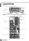
Rear Panel Top Panel
Front Panel