


English
Controls and Functions
Owner’s Manual
19
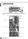
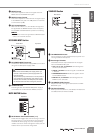
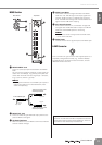
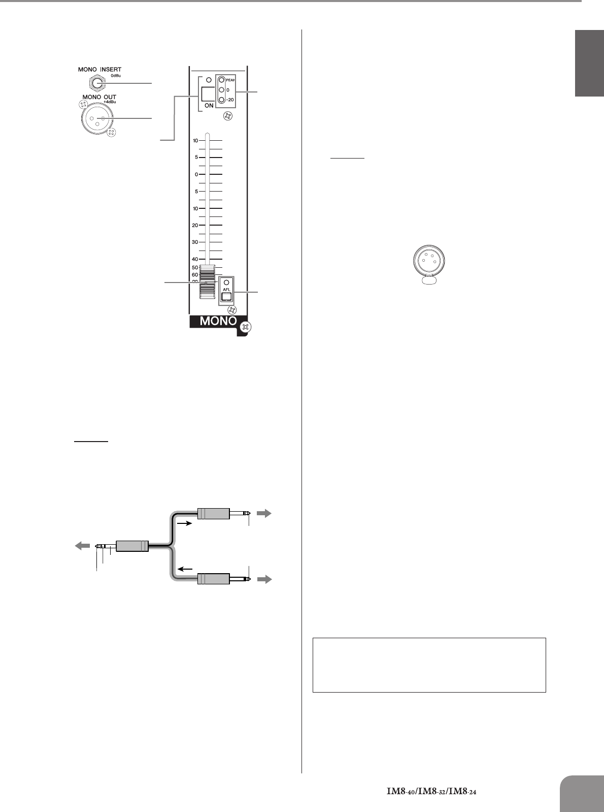
MONO Section
1
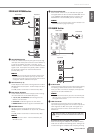
MONO INSERT Jack
This is an input/output jack located before the MONO
fader.
You can connect a graphic equalizer or other signal pro-
cessor. This is a TRS (tip, ring, sleeve) phone jack that
carries both the send and return signal (tip = send/out;
ring = return/in; sleeve = ground).
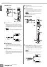
NOTE
· Patching external devices via an INSERT jack requires a
special insert cable such as illustrated below (insert
cable sold separately).
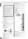
2 MONO OUT Jack
This is an XLR-3-32 type balanced output jack that out-
puts the MONO OUT signal.
3 ON Switch/Indicator
When this switch is on, the MONO OUT will be enabled
and the indicator will light.
4 MONO Level Meter
Three LEDs indicate the signal level after the MONO
fader. The “-20” LED will light if the output signal level
reaches -20 dB, and the “0” LED will light at nominal
level. The PEAK LED will light red when the MONO OUT
signal reaches 3 dB before clipping.
5 AFL Switch/Indicator
When the AFL switch is on, the indicator will light and
the signal after the MONO fader is output to the MONI-
TOR OUT and PHONES jacks for monitoring.
NOTE
· If you want to monitor the signal after the MONO fader,
turn off all PFL switches.
6 MONO Fader
Controls the level of the signal output to the MONO jack.
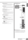
LAMP Connector
This is an XLR-4-31 type connector that supplies power to a
separately sold gooseneck lamp (e.g., Yamaha LA5000).
The IM8-40 mixer has three of these connectors, and the
IM8-32/24 mixers have two.
1
2
3
6
4
5
Rear Panel Top Panel
To the input jack of the
external processor
To the INSERT jack
Tip: OUT
Tip: IN
To the output jack of the
external processor
Sleeve (Ground)
Ring: IN
Tip: OUT
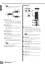
Impedance balanced:
Since the hot and cold terminals of impedance balanced
output jacks have the same output impedance, these out-
put jacks are less affected by induced noise.