


English
Controls and Functions
Owner’s Manual
13
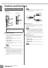
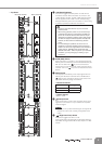
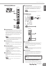
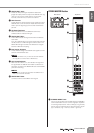
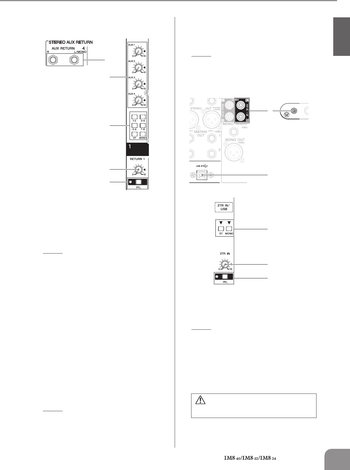
STEREO AUX RETURN Section
1
AUX RETURN Jacks
These are unbalanced phone-jack type line inputs. Sig-
nals input from these jacks can be sent to the GROUP 1/
2–7/8, ST L/R, MONO, and AUX 1–4 buses. To the
MONO and AUX 1–4 buses, a mix of the L/MONO and R
signal is sent. These jacks are typically used to receive
the signal returned from an external effect device
(reverb, delay, etc.).
NOTE
· These jacks can also be used as auxiliary stereo inputs.
· If you connect to the L/MONO jack only, the mixer will
recognize the signal as monaural and will send the identi-
cal signal to both the L/MONO and R jacks.
2 AUX Controls (1–4)
These adjust the level at which the signals from the AUX
RETURN jacks are sent (with L and R mixed) to the AUX
1–4 buses.
The “▼” position of the knob is nominal level (0 dB).
3 Bus Assign Switches
These switches determine the bus(es) to which the sig-
nal is received from the AUX RETURN jacks.
• 1-2, 3-4, 5-6, 7-8 switches: Send the signal to the
GROUP 1/2–7/8 buses.
• ST switch: Sends the signal to the ST L/R bus.
• MONO switch: Sends the signal to the MONO bus.
4 RETURN Control
Adjusts the level of the signal sent from the AUX
RETURN jacks to the GROUP 1/2–7/8, ST L/R, or MONO
buses.
The “▼” position of the knob is nominal level (0 dB).
NOTE
· The signals sent to AUX 1–4 are not affected by the
RETURN control.
5 PFL Switch/Indicator
When the PFL switch is on, the indicator will light and
the signal before the AUX controls and RETURN control
in the STEREO AUX RETURN section is output to the
MONITOR OUT and PHONES jacks for monitoring.
NOTE
·When you turn on the PFL switch, the PFL indicator in the
MONITOR section (page 18) will light.
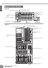
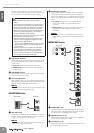
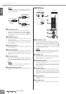
2TR IN/USB Section
1
2TR IN Jacks
These are RCA pin jacks and a mini-phone jack (stereo)
for inputting a stereo audio source. Use these jacks
when you want to connect a CD player, and output the
signal to the ST L/R or MONO bus.
NOTE
· If signals are simultaneously input from the 2TR IN jacks
(RCA pin jacks, mini-phone jack) and the USB connector,
the signals will be mixed.
2 USB Connector
Connects to the computer via the included cable to
input and output the signals. This connector outputs the
same signal as the REC OUT jacks. The signal input
from this connector is sent to the ST L/R bus or the
MONO bus.
Precautions when using the USB connector
When connecting the computer to the USB connector,
make sure to observe the following points. Failing to do
so risks freezing the computer and corrupting or losing
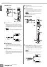
1
3
4
5
2
Rear Panel Top Panel
When connecting or disconnecting the USB cable
be sure to turn the 2TR IN/USB control all the way
down.
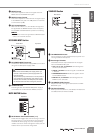
2
3
4
5
1
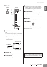
Top Panel
Rear Panel
Front Panel