


M2500—Owner’s Manual 25
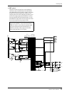
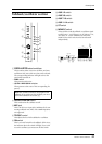
Rear panel
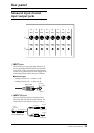
Monaural input channel
input/output jacks
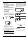
A INPUT jacks
These are XLR-3-31 type input jacks (balanced). If
the rear panel PHANTOM MASTER switch and the
+48 V switch of the corresponding monaural input
channel are on, phantom power will be supplied. The
nominal input levels and pin wiring are as follows.
■ Nominal input
• –26 dB pad switch= on / +10 dB to –34 dB
• –26 dB pad switch= off / –16 dB to –60 dB
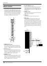
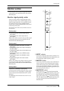
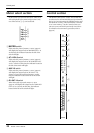
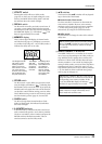
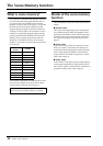
B INSERT I/O jacks
These are TRS phone jacks for inserting external
effect units into each monaural input channel. The
nominal level is 0 dB. The pin wiring is as follows.
17
INPUT
INSERT
I/O
0dB
18
INPUT
INSERT
I/O
0dB
19
INPUT
INSERT
I/O
0dB
20
INPUT
INSERT
I/O
0dB
21
INPUT
INSERT
I/O
0dB
22
INPUT
INSERT
I/O
0dB
23
INPUT
INSERT
I/O
0dB
24
INPUT
INSERT
I/O
0dB
2
1
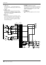
Male XLR plug
1 (ground)
3 (cold)
2 (hot)
1/4" phone plug
1/4" phone plug
1/4" TRS phone plug
To processor’s input
From processor’s output
Connect to INSERT I/O jack
Tip (send)
Tip (send)
Ring (return)
Sleeve (ground)
Sleeve (ground)
Tip (return)
Sleeve (ground)