


Yamaha Professional Audio M7CL StageMix V4.5 User Guide
Page 29
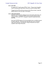
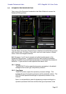
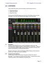
5.5 DYNAMICS PROCESSORS
When DYN mode is selected using the buttons described in section 5.0, the
status of both of the channel’s dynamics processors can be seen:
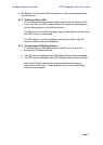
Dynamics 1 is displayed at the top of the thumbnail with Dynamics 2 at the
bottom. (Output channels have only Dynamics 1.)
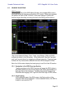
The threshold parameter value for each Dynamics is displayed numerically
and also graphically via a white vertical line.
A horizontal meter bar displays the input level to each Dynamics processor
moving from left to right. This bar is dimmed if the Dynamics processor is Off.
Alternatively, this horizontal meter bar can display the level of the Key-In
signal going to a dynamics processor. This can be selected for all channels
globally using a Preference on the SETUP screen: Display Key Input for
Dynamics Meters (refer to 9.13).
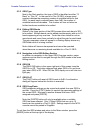
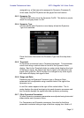
For all dynamics types except Gates, an orange horizontal meter bar displays
the amount of Gain Reduction, moving from right to left. This bar is not visible
when the Dynamics processor is Off.
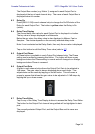
For Gates, three colour bars in green, yellow and red indicate the state of the
Gate. Only one of these bars will be lit at any time depending on the
opened/closed status of the Gate.
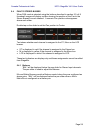
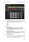
Dynamics Processor Type
When either Dynamics section is assigned to a Dynamics Type other than a
Gate or Compressor, text will be displayed to indicate the Dynamics Type.
The text labels are as follows:
DUCK = DUCKING
EXP = EXPANDER
DeES = DE-ESSER
CMPND = COMPANDER