


MV800 — Owner’s Manual
2 MV800
Features
• The MV800 provides 8 channels with monaural input jacks, A/B stereo
line input jacks and two sets of stereo outputs that are selectable from
the front panel.
• Monaural input jacks are equipped with an input select switch that
allows compatibility with a wide range of sources such as dynamic
microphones, condenser microphones that require an external power
source, and line level devices.
• Each monaural channel is equipped with a separate noise gate switch
that can be used to eliminate background noise.
• The mixer is equipped with a global compressor circuit that can be
applied to the monaural channels to protect the equipment from
feedback, sudden loud sounds, etc.
• The mixer is equipped with a ducker circuit on channels 1/2. This
function automatically reduces the volume level of the stereo line input
jacks when a microphone from channel 1 or 2 is used.
• Input channels 1-8 are equipped with INSERT IN/OUT jacks allowing
separate effectors to be connected to individual channels.
• Equipped with two ZONE buses, that include not only monaural and
stereo channels but also REC OUT and OUTPUT jacks, a single MV800
easily provides sound control for two rooms.
• Separate REC OUT jacks are supplied for both ZONES 1 and 2 allowing
easy recording to a tape deck.
• Along with XLR and phone jacks, Euro-block connectors are also
supplied for the main input and output jacks.
• The MV800 is equipped with a paging function for an emergency
announcement system. It is also equipped with an input jack for an
emergency announcement system’s control signal (DC24V).
• A security cover is supplied to protect switches and settings on the
control panel.
Contents
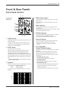
Front & Rear Panels ............................ 3
Front Panel Section ................................ 3
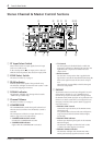
Stereo Channel &
Master Control Sections..................... 4
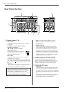
Rear Panel Section ................................ 6
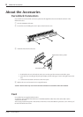
About the Accessories ........................ 8
About the MV800’s Functions ........... 9
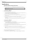
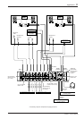
Applications .......................................... 10
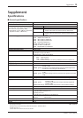
Supplement .......................................... 13
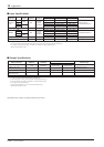
Specifications ....................................... 13
Dimensions .......................................... 15
Block and Level Diagrams.................... 16
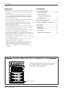
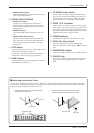
Caution: When the unit is installed in a rack
The main unit’s power switch is located on the rear panel of
the unit. When installed in a rack, please use the external
power switch on a power distributor, etc.
Power distributor, etc.