


MV800 — Owner’s Manual
Front & Rear Panels 7
•
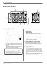
STACK OUT
This is an unbalanced phone type output jack with a
nominal input/impedance of 0dB/10kΩ.
It sends the ZONE 1 and ZONE 2 bus signals that
have passed through the compressor circuit. The
ZONE 1 signal is sent to the Tip while the ZONE 2
signal is sent to the Ring. When multiple MV800s are
connected together, this jack sends the signal to the
main MV800. It can also be used to send the signal to
an external device.
r PAGING Input
• MIC/LINE Input Jack
Connect the source device (cassette deck, etc.) or
microphone that will be used when the paging
function is in use.
This jack is compatible with 50Ω to 600Ω micro-
phones or 600Ω line level devices.
• Input Select Switch
Selects the type of microphone or device connected to
the MIC/LINE input jack. This switch functions in the
same manner as the Input Channel’s Input Select
Switch q.
• CONTROL IN Jack
This is the input jack for the emergency announce-
ment system’s control signal (DC24V).
t REC OUT (1L/1R, 2L/2R) Jacks
With an external DAT recorder or cassette recorder
connected to these jacks, you can record the same signal
that is sent from the ZONE OUT jacks. The signal from
ZONE 1 is sent to the 1L and 1R jacks while the ZONE 2
signal is sent to the 2L and 2R jacks. The signal sent from
these jacks is not affected by the ZONE volume controls.
Make recording level adjustments on the recording
device. Also, the ZONE 1 TO 2 switch is ineffective with
these jacks.
y ZONE OUTPUT Jacks
(ZONE 1 L/R, ZONE 2 L/R)
These jacks deliver the stereo output of the mixed signal
and are connected to a power amplifier, etc. that drives
the main speakers.
Two types of jacks are provided; balanced XLR type and
Euro-block connectors.
•
XLR type (1: Ground, 2: Hot, 3: Cold)
Nominal output/impedance +4dB/600Ω
•
Euro-block connector
(
: Hot, : Cold, G: Ground)
Nominal output/impedance +4dB/600Ω
u POWER Switch
When the switch is in the ON position, the unit is
powered.
When turning the power ON, first turn on the MV800,
then turn on the power amp or powered speakers that
are connected to the device.
Also, when turning the power OFF, turn off the power
amp or powered speakers before turning off the MV800.
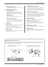
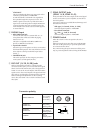
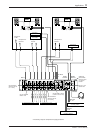
Connector polarity
INPUT, ZONE OUT
Pin 1: ground
Pin 2: hot (+)
Pin 3: cold (–)
INSERT IN
INSERT OUT
Tip: hot (+)
Ring: cold (–)
Sleeve: ground
STACK IN
STACK OUT
Tip: ZONE 1
Ring: ZONE 2
Sleeve: ground
PHONES
TipSleeve
Ring
Tip: L
Ring: R
Sleeve: ground
INPUT OUTPUT