


MV800 — Owner’s Manual
Front & Rear Panels 5
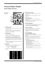
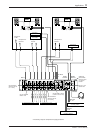
• PAGING LEVEL Control
Controls the output level of the PAGING MIC/LINE
input and adjusts the volume.
i PAGING INPUT DUCKER
• PAGING TH Control
Sets the level at which the mixer switches to its
PAGING function. Rotating the knob to the right
lowers the level at which the mixer will switch to the
paging function.
• PAGING Indicator
The indicator lights when the paging function is in
use.
• PAGING ZONE Select Switch
Selects the zone to which the PAGING MIC/LINE
signal will be sent. The PAGING MIC/LINE signal is
sent to the zone output jacks (ZONE 1, 2) that are
switched ON.
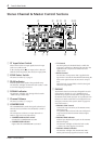
o LEVEL Meter
This LED indicates the level of the output signal for each
of the ZONE output jacks (ZONE 1,2).
“0” indicates a nominal level, and the PEAK indicator
will light red to warn when clipping is imminent.
!0 ZONE Volume
Controls the volume level of the signal that is sent to the
ZONE output jacks (ZONE 1, 2).
!1 ST/MONO Select Switch
Set the switch to ST when the signal from the ST Input
jack is to be sent to the ZONE output jacks (ZONE 1, 2)
as a stereo signal. Set the switch to MONO when the L
and R channels are to be mixed as a monaural signal.
!2 ZONE 1 TO 2 Switches
Set the switch to its ON (>) position to send the signal
from ZONE 1 (pre-volume) to ZONE 2 (pre-volume). In
this case, the ZONE 1 (pre-volume) signal will be sent to
the ZONE 2 output jacks and that signal’s volume can be
adjusted with the ZONE 2 Volume control.
!3 POWER Indicator
The indicator will light when the unit’s power is ON.
!4 ZONE AFL Select Switch
Selects the signal that is sent to the PHONES jack.
Press the switch to select either ZONE 1 (?) or ZONE 2
(>).
!5 HEADPHONE Volume
Controls the signal level that is sent to the PHONES jack.
!6 PHONES Jack
This is a stereo phone type jack for connecting a pair of
headphones (nominal output/impedance of 30mW/
40Ω).
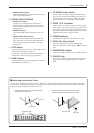
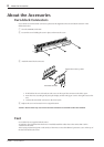
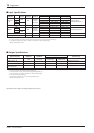
■ Attaching the Security Cover
The MV800 is supplied with a security cover for channels 1-8, the ST channel, and the compressor and paging sections. If the
security cover is needed to protect knobs and switches from being tampered with, attach the security cover after connecting
and setting up the microphones and line devices, etc.
1. Attach the post screws to the attachment holes (4
locations) on the front panel.
2. Align the holes in the security cover with the post
screws and attach the cover with the set screws.
Front panel
Post screw
Attachment hole
Security cover
Set screw