


105
Bitmap Window
The VL70-m Bitmap Window function makes
it possible to display 16 x 16 dot icons and
simple animation sequences on the VL70-m
display in the PLAY mode. The bitmap data can be
transmitted in the form of a data string from an
external MIDI device, and will appear on the
VL70-m display for about 3 seconds.
■ Bitmap Window Data Format
The format for message window data is as follows
(hexadecimal format):
F0 43 1n 4C 07 00 00 xx xx .... xx xx F7
“n” is the device number minus one. If the VL70-
m device number is set to “1”, for example, “n”
should be “0”.
“xx xx .... xx xx” is the bitmap data consisting of a
string of 48 2-digit hexadecimal bytes.
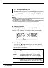
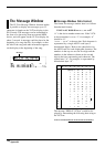
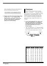
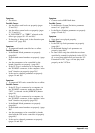
■ Creating Bitmap Data
1. Block out the desired design on a 16 x 16
grid, as shown in the example below.
2. Filled squares will be represented by ones,
and empty squares by zeroes.
1
2
3
4
5
6
7
8
9
10
11
12
13
14
15
16
12345678910111213141516
Icon
1
2
3
4
5
6
7
8
9
10
11
12
13
14
15
16
12345678910111213141516
0000001111000000
0001110000110000
0110000000001100
1000000000000010
0000000000000001
0000001111000000
0000111111110000
0001001111001000
0010011111100100
0100010100100010
1000011100100001
0100011100100010
0010011111100100
0001001111001000
0000111111110000
0000001111000000
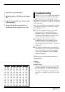
3. Divide the design horizontally into three
sections: two seven-columns and one two-
columns in width. Add one column of squares
the left of each section, and 5 columns to the
right of the 2-column section, as shown in
the example below. You now have 48 rows,
each 8 columns in width.
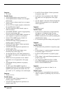
4. Use the chart below to convert the ones and
zeroes in each row from binary format to
hexadecimal format. The “bits” in columns 0
through 3 become the first digit, and the bits
in columns 4 through 7 become the second
digit of each hexadecimal byte.
For example, the 11th row in the example
forms the binary byte:” “01000011”. Columns 0
through 3 form “0100”, which, using the chart,
becomes hexadecimal digit “4”. Columns 4
through 7 form “0011”, which, using the chart,
becomes hexadecimal digit “3”. The 11th row
in the design can therefore be represented by
hexadecimal byte “43”.
1
2
3
4
5
6
7
8
9
10
11
12
13
14
15
16
17
18
19
20
21
22
23
24
25
26
27
28
29
30
31
32
33
34
35
36
37
38
39
40
41
42
43
44
45
46
47
48
0
0
0
0
0
0
0
0
0
0
0
0
0
0
0
0
0
0
0
0
0
0
0
0
0
0
0
0
0
0
0
0
0
0
0
0
0
0
0
0
0
0
0
0
0
0
0
0
0
0
0
3
0
0
0
0
0
0
0
0
0
0
0
0
0
0
0
0
4
0
0
0
0
0
0
0
0
0
0
0
0
0
0
0
0
5
0
0
0
0
0
0
0
0
0
0
0
0
0
0
0
0
6
0
0
0
0
0
0
0
0
0
0
0
0
0
0
0
0
7
0
0
0
0
0
0
0
0
0
0
0
0
0
0
0
0
1234567 1234567 12
0000001 1110000 00
0001110 0001100 00
0110000 0000011 00
1000000 0000000 10
0000000 0000000 01
0000001 1110000 00
0000111 1111100 00
0001001 1110010 00
0010011 1111001 00
0100010 1001000 10
1000011 1001000 01
0100011 1001000 10
0010011 1111001 00
0001001 1110010 00
0000111 1111100 00
0000001 1110000 00
Added
columns
binary hexadecimal
format format
0000 0
0001 1
0010 2
0011 3
0100 4
0101 5
0110 6
0111 7
binary hexadecimal
format format
1000 8
1001 9
1010 A
1011 B
1100 C
1101 D
1110 E
1111 F
Appendix