


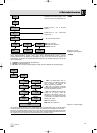
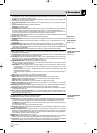
2.3 Optional Accessories
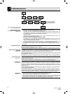
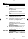
2.4 WMS 400
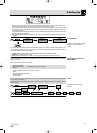
2.5 SR 400 Receiver
• Controls
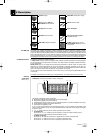
Front Panel
Refer to fig. 1.
The WMS 400 wireless microphone system comprises the SR 400 stationary diversity receiver,
HT 400 handheld transmitter with a D 880 or C 900 microphone element, and the PT 400 bodypack trans-
mitter. The receiver and transmitters operate in a 30 MHz subband of each frequency set within the 650
MHz to 863 MHz UHF band. You can select the receiving frequency from the preprogrammed frequency
groups and subchannels of your receiver or set it directly in 25 MHz-increments. Both the handheld and
the bodypack transmitter are set to the parameters selected on the receiver via infrared transmission.
The receiver provides two operating modes:
In LOCK mode, all setup functions are electronically locked to prevent parameters from being readjust-
ed unintentionally during a performance or lecture. The "LOCK" label on the display indicates the receiv-
er is in LOCK mode.
SETUP mode allows you to adjust and save all receiver parameters. In SETUP mode, the "LOCK" label
disappears. An infrared transmission link tunes the handheld or bodypack transmitter to the same fre-
quency as the one you selected on the receiver. You can also set the handheld transmitter audio input
gain on the receiver and transmit the setting to the transmitter via infrared.
You can use the receiver as a standalone unit or install it in a 19" rack using the supplied RMU 400 rack
mounting kit.
The display is protected from scratching by a transparent foil. You can peel the foil off at any time.
1 POWER: Switches power to the unit on or off.
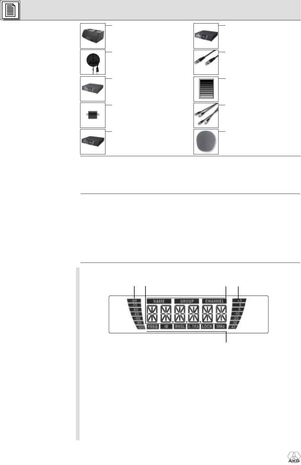
2 LCD display: The receiver provides a backlit LCD display.
The display indicates all receiver parameters:
a RF bargraph indicating the field strength of the received signal
b Alphanumeric display of the current setting
c Preset/Receiver Name, Frequency Group, Subchannel (shown in Preset and NAME screens only)
d Audio bargraph indicating the received audio level
e Parameter to be adjusted, mode
If one or more warning functions are activated (see section 4.1.3), the display will be backlit in red
when a critical condition occurs. As long as all parameters are within their normal ranges, the display
is backlit in green.
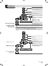
3 : These three keys set the various parameters of the receiver.
• In LOCK mode:
Short push on or : scrolls through the Frequency, Preset, and receiver Name screens.
Long push on : toggles between LOCK and SETUP modes.
• In SETUP mode only:
Short push on : Calls up a parameter for adjustment or confirms a selected value.
Short push on : selects a menu item or increases a parameter value.
Short push on : selects a menu item or decreases a parameter value.
2 Description
20
WMS 400
a c
d
e
b
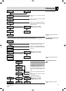
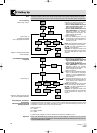
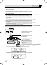
• CU 400 charger
• SRA 1 (shown), SRA 2 B,
RA 4000 B remote antennas
• PS 4000 antenna splitter
• AB 4000 antenna booster
• HPA 4000 headphone amplifier
• PSU 4000 central power supply
• MK PS antenna cable
• Color Coding Kit
• Front panel mounting kit for
supplied antennas
• W 880 windscreen for HT 400,
remote MUTE switch for PT 400
(not shown)
6393_04_BDA_Kern_wm 30.04.2004 10:04 Uhr Seite 20