


3 Setting Up
3.9 Setting Up the Transmitter
Note:
3.9.1 Frequency
Refer to figs. 3 and 4.
Refer to figs. 10
(handheld transmitter)
and 11 (bodypack transmitter).
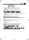
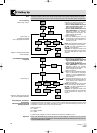
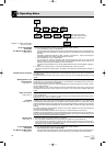
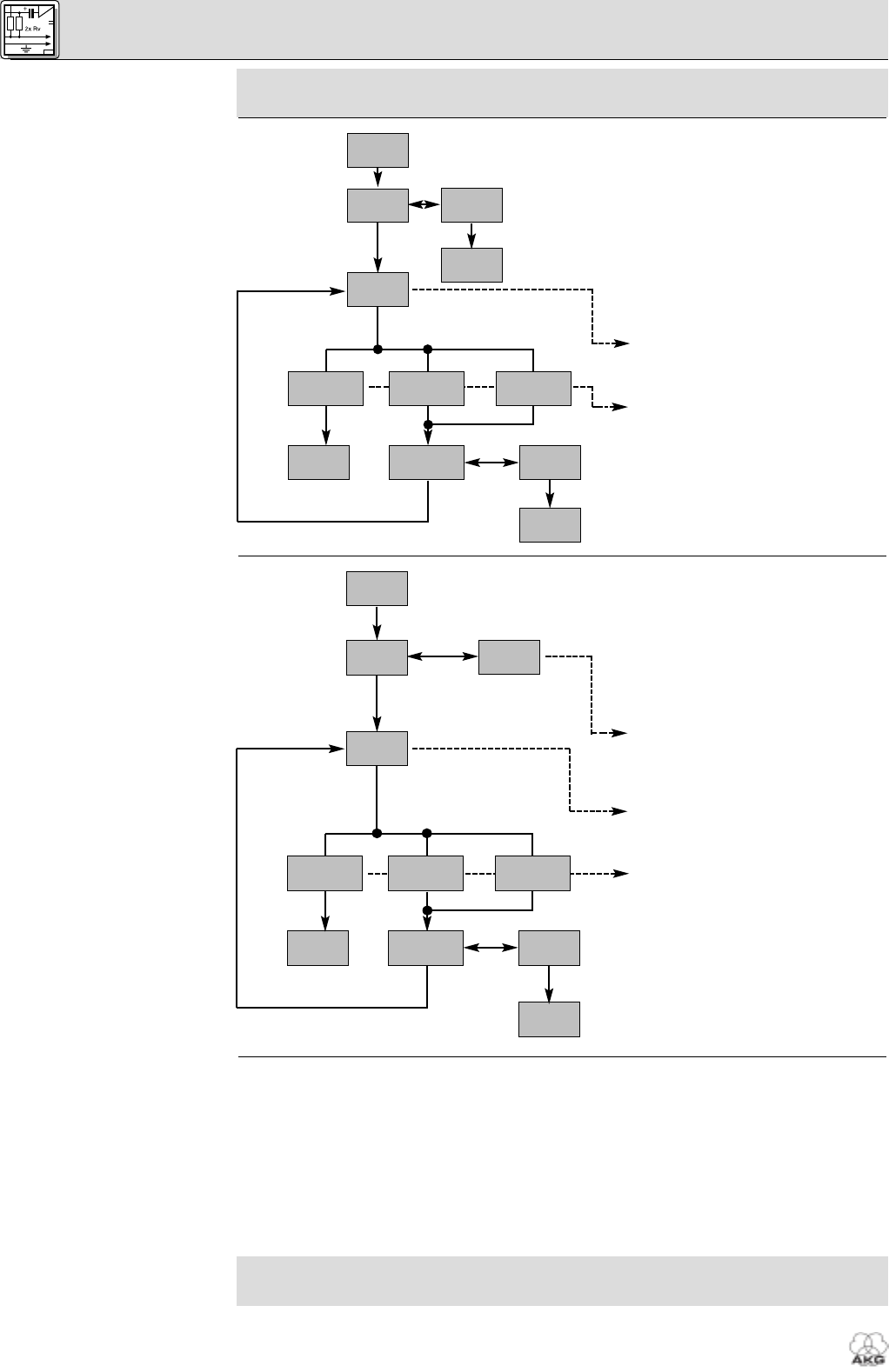
Diagram 7: Setting the transmitter
carrier frequency.
3.9.2 Handheld Transmitter
Input Gain
Refer to fig. 10.
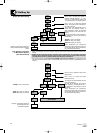
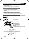
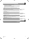
Diagram 8: Setting the audio input
gain on the handheld transmitter.
3.9.3 Bodypack Transmitter:
Connecting a
Microphone/Instrument and
Setting Input Gain
Important!
Section 3.9.1 applies to both the HT 400 handheld transmitter and the PT 400 bodypack transmitter. To set
the audio input gain on the HT 400, use the TX Gain screen on the receiver and the infrared connection.
To set the audio input gain on the PT 400, use the gain control in the transmitter battery compartment.
To program the transmitter for the same
frequency you selected on the receiver:
1. Switch power to the receiver on.
2. Set the ON-MUTE/PRG-OFF switch
(19) on the transmitter to "OFF". The
status LED (20) will extinguish.
3. Set the ON-MUTE/PRG-OFF switch
(19) to "MUTE/PRG". The display will
alternately indicate the currently
selected frequency and "Prg IR". The
status LED (20) remains dark.
4. Refer to Diagram 7.
5. Point the infrared sensor (1) on the
transmitter at the infrared emitter (2)
on the receiver from a distance of 4
inches (10 cm) max.
IR OK: The transmitter has been tuned
to the same frequency as the receiver.
IR ERR: The data transmission has
failed (no communication).
TXBAND: The frequency bands of the
transmitter and receiver are not identi-
cal or the transmitter RF output is too
high/low.
1. Switch power to the receiver on.
2. Set the ON-MUTE/PRG-OFF switch
(19) on the transmitter to "OFF". The
status LED (20) will extinguish.
3. Set the ON-MUTE/PRG-OFF switch
(19) to "MUTE/PRG". The display will
alternately indicate the currently
selected frequency and "Prg IR". The
status LED (20) remains dark.
4. Refer to Diagram 8.
5. Select "HI" for a handheld transmitter
with a D 880 dynamic microphone
element or "LO" for a handheld trans-
mitter with a C 900 condenser micro-
phone element.
6. Point the infrared sensor (1) on the
transmitter at the infrared emitter (2)
on the receiver from a distance of 4
inches (10 cm) max.
IR OK: The transmitter has been tuned
to the same frequency as the receiver.
IR ERR: The data transmission has
failed (no communication).
TXBAND: The frequency bands of the
transmitter and receiver are not identical
or the transmitter RF output is too
high/low.
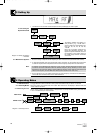
The PT 400 bodypack transmitter has been designed primarily for use with "L" type MicroMic Series
microphones from AKG (see section 2.7). If you wish to connect other microphones from AKG or other
manufacturers to the PT 400, please note that you may have to rewire the existing connector of your
microphone or replace it with a 3-pin mini XLR connector.
Audio input pinout:
Pin 1: shield
Pin 2: audio (inphase)
Pin 3: audio
A positive supply voltage of 6 volts for condenser microphones is available on pin 2.
Please note that AKG cannot guarantee that the PT 400 bodypack transmitter will work perfectly
with products from other manufacturers and any damage that may result from such use is not cov-
ered by the AKG warranty scheme.
26
WMS 400
>TXGAIN<
IR
IR
IR
IR
TXG >LO<
EXITRETRY
IR OK
IR
TXBAND
IR
IR ERR
IR
>I>---<
TXG >HI<
PRG IR
IR
IR
IR
IR
IR
IR
IR
>EXIT<
EXITRETRY
IR OK
IR
TXBAND
IR
IR ERR
IR
>I>---<
>PRG IR<
IR
6393_04_BDA_Kern_wm 30.04.2004 10:04 Uhr Seite 26