


3 Setting Up
Important!
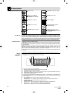
3.1 Inserting the Transmitter
Battery
Refer to fig. 5.
Note:
3.2 Positioning the Receiver
Note:
3.3 Rack Mounting
3.3.1 Single Receiver
Refer to fig. 6
3.3.2 Two Receivers Side by
Side
Refer to fig. 7.
Note:
3.4 Connecting the Receiver
to a Mixer
Refer to figs. 8.
3.5 Connecting the Receiver
to Power
Refer to fig. 9.
3.6 Powering Up the Receiver
Note:
Refer to fig. 1.
Prior to setting up your WMS 400, check that the transmitter and receiver are tuned to the same fre-
quency, referring to sections 3.8 and 3.9.
1. Open the battery compartment cover (1).
2. Insert the supplied battery (2) into the battery compartment, aligning the battery with the polarity sym-
bols.
If you insert the battery the wrong way, the transmitter will not be powered.
3. Close the battery compartment cover (1).
Alternatively to the supplied dry battery, you may use a commercial 1.2 V AA size, ≥2100 mAh
rechargeable battery.
Reflections off metal parts, walls, ceilings, etc. or the shadow effects of musicians and other people may
weaken or cancel the direct transmitter signal.
For best results, place the receiver or remote antennas as follows:
1. Place the receiver/antennas near the performance area (stage). Make sure, though, that the transmit-
ter will never get any closer to the receiver than 10 ft (3 m). Optimum separation is 16 ft. (5 m).
2. Check that you can see the receiver from where you will be using the transmitter.
3. Place the receiver at least 5 ft. (1.5 m) away from any big metal objects, walls, scaffolding, ceilings,
etc.
You can either use the receiver freestanding or mount it in a 19" rack using the supplied RMU 400 rack
mounting kit.
If you install one or ore receivers into a 19" rack, either mount the supplied antennas on the receiver front
panel(s) or use remote antennas. This is the only way to ensure optimum reception quality.
1. Unscrew the four rubber feet (1) from the receiver bottom panel.
2. Unscrew the two fixing screws (2) from each side panel.
3. Use the fixing screws (2) to screw the short bracket 3 to one side panel and the long bracket (4) to the
other side panel. The brackets are contained in the supplied rack mounting kit.
4. Install the receiver in your rack.
1. Unscrew the four rubber feet (1) from each receiver's bottom panel and remove the screws (5) from
the rubber feet (1).
2. Unscrew the two fixing screws (2) from the right-hand side panel of one receiver and from the left-
hand side panel of the other receiver.
3. Remove the plastic covers 3 from the side panels with the fixing screws (2) still on.
4. Insert one connecting strip (4) into each free slot in the side panel of the first receiver, making sure to
align the hole in each connecting strip 4 with the appropriate threaded hole in the receiver bottom
panel.
5. Fix the connecting strips (4) on the first receiver using the screws (5) you removed from the rubber
feet.
6. To join the two receivers, slide the connecting strips (4) on the first receiver through the free slots in
the side panel of the second receiver. Make sure to align the hole in each connecting strip (4) with the
appropriate threaded hole in the bottom panel of the second receiver.
7. Fix the connecting strips (4) on the second receiver using the screws (5) you removed from the rub-
ber feet (1).
8. Screw a short bracket (6) to the outer side panel of each receiver using for each bracket two of the
screws (2) you removed from the receiver side panels.
9. Install the receivers in your rack.
Be sure to keep the remaining screws (5) for later use.
Connect the audio output to the desired input:
- BALANCED socket (1) - XLR cable - microphone input: set output level switch (2) to "-30 dB".
- BALANCED socket (1) - XLR cable - line input: set output level switch (2) to "0 dB".
- UNBALANCED jack (3) - 1/4" jack cable - unbalanced 1/4" microphone or line input jack.
1. Check that the AC mains voltage stated on the included power supply is identical to the AC
mains voltage available where you will use your system. Using the power supply with a differ-
ent AC voltage may cause damage to the unit.
2. Plug the feeder cable (1) on the included power supply into the DC IN socket (2) on the receiver rear
panel and screw down the DC connector (3).
3. Plug the power cable on the power supply into a convenient power outlet.
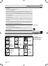
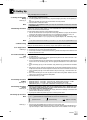
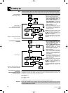
In the display illustrations in the following sections, flashing characters are identified by angle symbols
">" and "<". Characters between quotation marks are examples of possible settings.
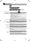
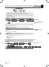
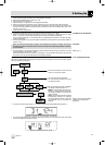
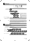
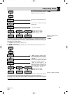
The following symbols are used in Diagrams 1-14:
1. Press the front panel POWER switch to switch power to the receiver ON.
Pressing POWER automatically places the receiver in Lock mode, and the display will indicate the cur-
rently active frequency in MHz and the "LOCK" label as shown in the screenshot on the next page.
22
WMS 400
press and hold press briefly press or briefly
6393_04_BDA_Kern_wm 30.04.2004 10:04 Uhr Seite 22