


17 DIGITAL PRO MIXER DDM4000 User Manual
Storing user settings:
Press the LOAD push button 1) (35) to access User Setup with its preset list.
Turn the CONSOLE SETUP knob 2) (51) to select a memory location.
Press the CONSOLE SETUP knob to store the user setting.3)
It is not possible to overwrite the factory preset.◊
Exiting User Setup:
Press the LOAD push button • (35) or the ESC push button (52)
to exit User Setup.
Operating the phones section3.6
You can use the headphones to listen to two dierent signals: 1. The PGM
signal (=Program): This is the signal at the MAIN output. 2. The PFL signal
(=Pre Fader Listen): This is the signal which can be routed to the PFL bus by using
the PFL push buttons (7). The PFL signal is fader-independent, which means it
can even be heard when the faders are pulled down.
When the SPLIT push button (40) is not pressed, both the PGM and PFL signal are
played back in stereo in the headphones. The mix of both signals is adjusted with
the MIX knob (38). When the knob is turned completely to the left, the PFL signal
is heard, whereas when turned completely to the right, the PGM signal is heard in
both headphones.
Working in Split Mode:
Press the SPLIT push button • (40) to activate Split Mode.
When using Split Mode, the PFL signal is played back on the left headphone
while the PGM signal is played back on the right headphone (both mono signals).
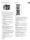
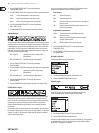
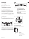
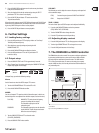
BPM and Eects4. Section
Fig. 4.1: BPM and Eects section
The BPM and Eects section in the middle of the mixer can either be used for
the stereo channels or the master signal. Both processors can also be combined
to be used as dual eect for individual channels. What’s more, both Microphone
channel and Sampler feature their own eect processors, which are described in
individual chapters (Chapter 3.3.1 and Chapter 5.4).
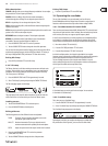
Display:
The display shows the following information:
A Shows the eect type and the parameter values.
B Shows the calculated speed in BPM (Beats Per Minute).
It Also gives information on the signal assignment and the
Tap function.
C This section shows the BPM-synchronized eect parameters as
beats on the right side. On the left, you see the activity of the
Kill function in the eect path.
D This information refers to the Sampler and/or the MIDI Clock
(see Chapter 5).
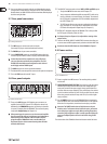
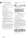
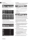
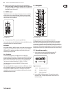
Eects section4.1
(51)(48)(47)(46)(41)
(50)
(44)
(49)(43)
(45)
(42) (53) (52)
Fig. 4.2: Eects section (here FX 1)
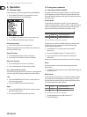
Selecting the signal source4.1.1
To use an eect, you rst have to assign the eect to a signal source.
This assignment also applies to the BPM Counter. Possible input sources
are as follows:
INPUT 1 – INPUT 4: Stereo channels 1 – 4.
MUSIC: Stereo sum signal (main signal).
CHAIN: CHAIN assigns the eect to the signal of the
other eects section, so that 2 eects are
triggered consecutively.