


18 DIGITAL PRO MIXER DDM4000 User Manual
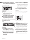
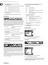
Selecting a signal for FX 1:
Press the FX 1 ASSIGN push button 1) (43).
Turn the left PARAMETER knob 2) (45) to select a signal source from the list.
Press the left PARAMETER knob to conrm the selection.3)
Selecting a signal for FX 2:
Press the FX 2 ASSIGN push button 1) (43).
Turn the right PARAMETER knob 2) (45) to select a signal source from the list.
Press the right PARAMETER knob to conrm the selection.3)
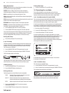
Activating an eect4.1.2
Press the FX ON push button 1) (42) to activate the eect. Both the FX ON
push button and the EFFECT/BAND push button (46) – (48) ash.
Turn the DEPTH knob slowly to the right until you hear the eect 2)
as is intended.
Kill function on the eect path:
A specially eective way of alienation is to remove individual frequency bands
from the eect processing. There are three additional Kill switches that are found
on the signal path leading to the eects unit. The EFFECT/BAND push buttons
of the activated eect ash blue corresponding to the frequency bands that are
active. By pressing the push buttons you are able to “kill” the frequency bands.
And the display shows the Kill function’s status.
Press one of the EFFECT/BAND push buttons (• (46), (47), (48) ) while the eect
is active. The push-button LED of the deactivated band goes out.
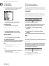
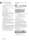
Selecting an eect4.1.3
Nine eect types are available. The eect table in Chapter 4.1.4 gives an
overview of the possible eects and their adjustable parameters.
Press the SELECT push button 1) (46). The display shows a list of all
types of eects.
Turn the PARAMETER knob 2) (45) to select the eect type.
Press the PARAMETER knob to load the eect type.3)
Eect descriptions4.1.4
The following gives you a description of the available eects and adjustable
parameters. (BPM-synchronized parameters are printed in italic.) The tables
show you which controls are used to adjust the parameters. Chapter 4.1.5
describes eect processing. Chapter 4.1.6 gives you the information you need
to know about BPM-synchronized parameters.
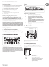
FLANGER, PHASER, PAN:
FLANGER: The anger eect is achieved by frequency modula-tion. You are able
to adjust the speed of the LFO (Low Frequency Oscillator), the amount of the
eect signal that is fed back to the input (Feedback), the eect depth (Depth)
and the degree of phase shifting represented in rhythmical units (Phase).
Use Fade in case you want the anger to complete its period of oscillation
after the eect has been turned o, to avoid an abrupt truncation of the eect.
PHASER is similar to the anger. In this case the modulation is achieved through
phase shifting. You can adjust the speed of the LFO and the eect depth (Depth).
Use Fade to determine if the eect is to end abruptly or softly fade out.
PAN specied an eect which lets the signal move from the right to the left side
of the stereo image. This eect sounds the most intensive when the DEPTH knob
is turned right up. LFO adjusts the speed of the panning and Depth adjusts the
eect depth.
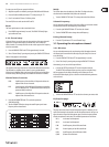
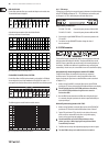
1/5 2/5 3/5 4/5 5/5
LFO Speed Feedback Depth Phase Fade Dry/Wet Mix
PHASER
LFO Speed Depth Fade — — Dry/Wet Mix
LFO Speed Depth — — — Dry/Wet Mix
PAN
FLANGER
Tab. 4.1: Eect parameters for Flanger, Phaser and Panning
DELAY, ECHO:
DELAY is a signal delay. The delay time (Time) can by synchronized with
the BPM Counter. A simple delay (Simple) and the 3-Pong Delay, which spreads
the delays across the whole stereo image, are available.
ECHO is similar to the delay. The only dierence is that the delayed signal is
repeated several times. Use Feedback to specify the number of times that the
delay is to be repeated. Fade determines if the echo is to fade out (On) or not
(O) when the eect is turned o.
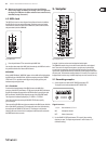
1/5
TIME
2/5
MODE
3/5
FDBK
4/5
FADE
DELAY
10...
5930 ms
Simple
3Pong
— — Dry/Wet Mix
ECHO
10...
5930 ms
Simple
3Pong
0 - 100% Dry/Wet Mix
Tab. 4.2: Eect parameters for Delay and Echo