


7 DIGITAL PRO MIXER DDM4000 User Manual
Stereo channels 1 – 42.1
(2)
(1)
(3)
(5)
(9)
(10)
(4)
(7)
(8)
(6)
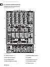
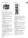
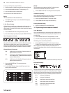
Fig. 2.1: Stereo channel strips
The input select switch lets you switch between two signal sources. (1)
Select Line to hear the signal of the Line input (67). Select Phono/Line to
listen to the incoming source signal at the Phono/Line (68) input.
The (2) GAIN knob adjusts the level of the input signal. The actual level
is displayed on the level meter (3).
The 7-segment LED meter indicates the level of the input signal.(3)
Each input channel features a 3-band equalizer (4) (HIGH, MID and LOW)
with kill feature, giving you up to 12 dB of boost and a maximum cut
of -∞ dB (kill). The kill feature lets you mute the given frequency range.
When each EQ knob is turned fully left, the signal is eectively muted.
All EQ parameters can be adjusted in Channel Setup.
The (5) MODE push button changes the functionality of the preset push button
(6) from Multi to Single.
The preset push buttons (6) P1, P2 and P3 allow you to store and activate
equalizer presets. When activated in Single Mode, these push buttons
provide a maximum cut of -∞ dB (kill function).
Press the (7) PFL push button to listen in on the channel’s signal
using headphones.
The fader controls the channel volume.(8)
The (9) CURVE switch adjusts the response of the fader. In SOFT Mode, the fader
responds slower to steady fader movement in the upper range and quicker in
the lower range. In Sharp Mode, the fader adjusts the volume quicker in the
upper third and slower in the lower range. In MID Mode, the fader responds
in a linear fashion. Since a dierence in volume levels is heard when
switching between modes, don’t use this switch while playing music!
The (10) CF ASSIGN push button lets you determine on which side of the
crossfader (20) (A or B the signal is to be heard.
Microphone channel2.2
(11) (12)
(13)
(16)
(17)
(18)
(19)
(15)
(14)
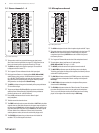
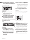
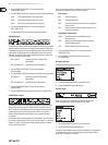
Fig. 2.2: Microphone channel
The (11) GAIN knob adjusts the level of the microphone signal at the MIC 1 input.
This switch determines which signal is to be displayed on the level meter (12) (13).
IN VU shows the unprocessed input level which helps you to adjust the
microphone signal correctly. XMC VU shows the level after it has passed
the Ultramic processor.
The 7-segment LED meter indicates the level of the microphone channel.(13)
The microphone channel strip features a 3-band equalizer (14)
(HIGH, MID and LOW). The range is +/-12 dB.
The (15) ON/OFF push button turns the microphone channel on and o.
The (16) MIC SETUP push button opens the Mic Setup menu on the display.
This allows you to adjust the settings of the equalizer, the Ultramic processor
and the MIC FX (eects processor).
The (17) XMC ON push button activates the ULTRAMIC processor, which includes
a 2-band compressor and expander. Ultramic settings can be adjusted in
Mic Setup.
The (18) MIC FX ON push button activates the microphone eects processor.
Select the eect in Mic Setup.
The (19) TALK ON push button activates the Talkover function. This attenuates
the volume level of the music as soon as you speak into the microphone.
This is a very useful function to make yourself heard over the music being
played. You can adjust all the relevant settings in Talk Setup.