


10
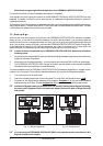
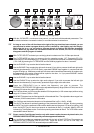
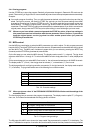
Fig. 1.3: Function keys and jog wheel
5
With the JOG WHEEL, a continuous rotary control, you can freely edit the selected parameters. Turn
the wheel clockwise to increase the values, or counterclockwise to reduce them.
+ As long as none of the edit functions to the right of the jog wheel has been selected, you can
use the wheel to select a program directly, which is shown by a dot lighting up in the display.
While this dot is on, you can select a program though its settings will not take immediate
effect. When the jog wheel has not been touched for one second, the LED in the display
disappears and the program is loaded.
6
With FILTERSELECT activated you use the jog wheel to select one of the 12 filters per channel.
7
The FILTERMODE key gives you access to the four operating modes: OF, Parametric EQ (PA),
Single-Shot (SI) and Auto Mode (AU). In addition you can edit the threshold of feedback suppression
(-3 to -9dB) by pressing the FILTERMODE and the GAIN key together for about 1 seconds.
11
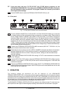
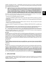
Use the ENGINE L key to select the left audio channel.
12
Use the ENGINE R key to select the right audio channel. If you wish to process the left and right audio
channels simultaneously (COUPLE mode), press both ENGINE keys together. In couple mode both
engine LEDs light up. Whenever you edit one of the two audio channels and then switch to couple mode,
the parameters of the active channel will be copied to the other; i.e. if you press ENGINE L before
ENGINE R, left will be copied to right.
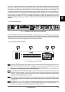
8
Use the ENGINEL key to select the left audio channel.
9
Use the ENGINER key to select the right audio channel. If you wish to process the left and right
channels simultaneously (Couple mode), press both Engine keys at the same time.
10
Press the FREQUENCY key to select the frequency you wish to process. The
FEEDBACKDESTROYERPRO splits up the adjustable frequency range (20Hz to 20kHz) into the 31
standard ISO values of a graphic EQ (see 6.1).
11
The FINE key allows you to fine tune the standard ISO frequencies (in 1/60-octave steps) within a tuning
range of 1/3 octave (-9/60 to +10/60).
12
BANDWIDTH determines the filter bandwidth of the selected filter. The adjustable value ranges from
2 octaves (120/60 octave) down to 1/60 octave.
13
The GAIN key sets the desired boost/cut of the selected filter indB (+16dB / -48dB).
14
The IN/OUT key allows for optional bypassing of the parametric filters or all filters. By shorty pressing
the IN/OUT key only the parametric filters will be deactivated and the green LED ends up lighting. Hold
down the IN/OUT key for about two seconds to deactivate all filters. A cyclically flashing LED will
indicate this Total-Bypass mode. One further pressing reactivates all filters. The LED flickers when
relevant MIDI data is received.
+ Please, use the Total-Bypass function only with utmost caution because by deactivation, the
FEEDBACK DESTROYER PRO possibly unlocks suppressed feedbacks.
15
Any modifications made to a preset can be stored with the help of the STORE key. Ten presets are
available on the FEEDBACK DESTROYER PRO. Press the IN/OUT and the STORE keys, the
FEEDBACK DESTROYER PRO automatically enters MIDI mode.
1. INTRODUCTION