


22
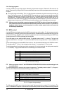
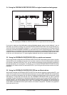
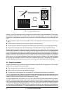
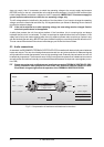
Microphone
Mixing Console
Power Amp
Speaker Box
Fig. 4.3: Typical feedback loop
Basically, any microphone signal passing through an amplifier is liable to generate feedback. Unfortunately,
the feedback frequencies of P.A. systems differ, and even one single system can have varying feedback
frequencies, as these depend largely on the room acoustics. Feedback can be caused by the following condi-
tions:
s The microphones are too close to the speaker boxes or the speakers are badly positioned (monitor sys-
tem).
s The microphone channels on the mixing console are not set up correctly.
s The microphones used are not operated in accordance with their directivity (e.g. cardioid/super-cardioid).
s The acoustic properties of the room are unfavorable. Tiled walls and floors heavily reflect the sound.
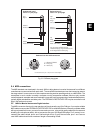
All rooms feature a number of natural resonances sometimes with high quality factor. At such frequencies the
potential risk of feedback is increased. In addition to the acoustic properties of the room, the relative position
of the microphone with reference to the loudspeaker plays a decisive role for the generation of feedback. In
practice, this phenomenon can be observed with microphone held directly in front of a speaker, thus producing
feedback. Of course, the first thing to do in such a case is to move the microphone away from the speaker.
When doing so, you can hear the feedback frequency change, because a variation in the distance between
microphone and loudspeaker results in a variation of feedback frequencies. It is therefore very difficult to
anticipate feedback frequencies and avoid their occurrence by means of equalizers with fixed settings.
4.2 Graphic equalizers
Graphic equalizers are part of the audio engineers standard equipment for live applications. In this context,
graphic EQs usually perform three main tasks:
s Fine tuning the mix to your taste and the style of music.
s Fine tuning the mix to the room and speaker acoustics.
s To some extent, audio engineers can use graphic EQs to manually suppress annoying feedback.
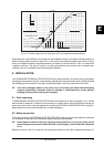
The 1/3-octave design with 31 faders per channel has become the standard among graphic equalizers. Here,
the spacing between individual filter frequencies is 1/3 octave. The quality factor (Q) of the filters (usually 1/3
octave) is fixed as are the frequencies controlled with the 31 filters.
1/3-octave equalizers are very popular (e.g. our ULTRA-CURVE PRO DSP8024) because they are so easy to
operate. The fader positions clearly show how the signal is being processed, especially since graphic EQs
have fixed frequencies based on the so-called ISO standard. So, all graphic equalizers designed to meet the
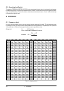
ISO standard feature the same fixed frequencies. Once youve got used to work with a 1/3-octave equalizer,
you will find the FEEDBACK DESTROYER PRO a highly convenient tool, as it splits up the audio spectrum
into the ISO frequencies (see table 1.2), which enables you to access the most important frequencies quickly.
4. TECHNICAL BACKGROUND