


25
E
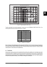
Quantization Steps
U (Voltage)
-8 -7 -6 -5 -4 -3 -2
Digital Words
1111
1110
1101
1100
1011
1010
1001
1000
0000
t (Time)
0001
0010
0011
0100
0101
0110
0111
Conversation Rate
8
7
6
5
4
3
1 2 3 4 5 6 7 8
-1
-2
-3
-4
-5
-6
-7
-8
Quantization Errors
(Noise)
Continuous
Analog Signal
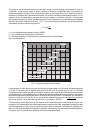
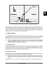
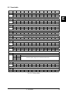
Fig. 4.4: Transfer diagram for an ideal linear ADC (2s complement representation)
Digital distortion is quite different, as illustrated by this simplified example. If we take the situation where a 4
bit word has the positive maximum value of 0111, and add to it the smallest possible value of 0001 (in other
words, the smallest increase in amplitude possible), the addition of the two results in 1000 - the value of the
negative maximum. The value is turned on its head, going instantly from positive max to negative max,
resulting in the very noticeable onset of extreme signal distortion.
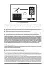
5. INSTALLATION
Your BEHRINGER FEEDBACKDESTROYERPRO was carefully packed in the factory and the packaging
was designed to protect the unit from rough handling. Nevertheless, we recommend that you carefully examine
the packaging and its contents for any signs of physical damage, which may have occurred in transit.
+ If the unit is damaged, please do not return it to us, but notify your dealer and the shipping
company immediately, otherwise claims for damage or replacement may not be granted.
Shipping claims must be made by the consignee.
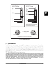
5.1 Rack mounting
The BEHRINGER FEEDBACKDESTROYERPRO fits into one standard 19" rack unit of space (1 3/4"). Please
allow at least an additional 4" depth for the connectors on the back panel. Be sure that there is enough air
space around the unit for cooling and please do not place the FEEDBACKDESTROYERPRO on high tem-
perature devices such as power amplifiers etc. to avoid overheating.
5.2 Mains connection
The mains connection of the FEEDBACKDESTROYERPRO is made by using a mains cable and a standard
IEC receptacle. It meets all of the international safety certification requirements.
+ Please make sure that all units have a proper ground connection. For your own safety, do not
remove the ground connection within the units or at the supply, or fail to make this connection
at all.
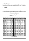
Before you switch on the unit, check that it is configured to match your AC mains voltage requirements. If it
5. INSTALLATION