


8
Electrostatic charges might affect the operation of the FEEDBACKDESTROYERPRO!
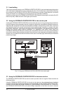
For further information on correct installation see chapter 5 Installation.
As a standard the audio inputs and outputs on the BEHRINGER FEEDBACKDESTROYERPRO are fully
balanced. If possible, connect the unit to other devices in a balanced configuration to allow for maximum
interference immunity.
The automatic servo function detects unbalanced connections and compensates the level difference automati-
cally (6dB correction). The MIDI links (IN/OUT/THRU) are made over standardized DIN patch cords. The data
communication is isolated from ground by opto couplers.
1.3 Hook up & go
We know you are anxious to get to work with your new FEEDBACKDESTROYERPRO, the band is probably
setting up now, youre half an hour behind schedule, it is hectic, dark and damp. If you promise to read the
whole manual tomorrow, or at least next week, we show you how to get up and go and get through this night
alive. If youve used a variety of PA gear, youll have the FEEDBACK DESTROYERPRO up and running after
quickly perusing the manual. If youre not so experienced, dont worry, it will come to you. In both cases, still
read the manual! The following may then help you get it happening with a minimum of fuss.
+ In order to use the full potential of your FEEDBACKDESTROYERPRO, please bear in mind the
following points:
1. No device will fully compensate for wrong microphone handling! Be aware that there are some actions on
stage may still result in feedback.
2. Allow some time for experimentation you may need to get used to the DSP1100P over several gigs.
3. The FEEDBACK DESTROYERPROs single shot filters are well suited to automatically attenuate
resonances which are most likely to cause feedbacks.
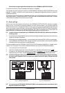
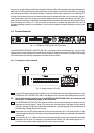
The most probable use for the FEEDBACKDESTROYERPRO is feedback suppression in a stage monitor
system or in a PA system. The unit should be placed between your console and the poweramplifiers.
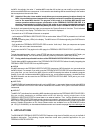
1. First, connect the unit as seen below.
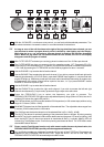
2. Check the operating level switch on the back panel. For most PAs, this should be set to +4dB.
3. On power-up, the Jog Wheel can select any of 10 programs. Programs 13 give you instant feedback
suppression for all 12 filters. Choose Program 8 or 10 for stereo processing of the master output.
+ Note that the Bypass switch can be either Off or On, but NOT flashing! When Bypass is flashing,
the whole unit is bypassed. But in the other two modes, filters set to Auto or Single Shot will
still operate.
Master Out
P.A. System
Monitor Out
Monitor System
Master Out
P.A. System
Fig. 1.1: Monitor application Fig.1.2: PA application
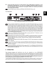
+ If you are using the FEEDBACKDESTROYERPRO for two separate monitor channels the L & R
Engines should not be coupled.
1. INTRODUCTION