


30
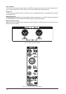
8. THE PATCHFIELD
Nomenclature clarification:
s FIELD = entire patching area
s BAY = a unit of 48 jack sockets arranged as 24 outs over 24 ins
If you really want to make the most of your home studio, invest in a patchfield. We know that you will often put
off doing a complex patch if there is no patchfield:
1) because its so much bother and
2) in case you inadvertently damage or pull out a lead.
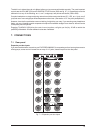
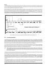
8.1 The normalized bay
Most decent jackbays offer two rows of 24 normalized jacks in a 1 U of rack space. Lucky youve got a 24/48
channel desk, eh? The term normalized refers to the fact that the top row (outputs) are internally connected to
the bottom row (inputs), unless you plug something into an input socket. Plugging into the output socket of a
normalized insert pair does not break the internal connection, but it does provide an alternative direct output.
Where normalizing is not wanted on a patchbay (there are a few cases!) it is possible to remove it by cutting
certain PCB tracks. Refer to the patchbay instructions for how to do this.
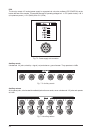
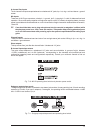
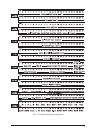
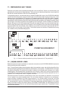
8.2 The patchfield
If you want to do the only decent thing and construct a patchfield for your studio, heres how to do it. Note that
we have laid it out in order that a minimum number of cables are likely to be needed. We have also completely
left out the microphone inputs. Unlike everything else, these operate at a level several orders of magnitude
lower than line (+4 dBu or -10 dBV). It is best to plug microphones directly into the EURODESK MX9000, or
via special XLR-type wall boxes connected to the EURODESK microphone inputs by a good quality balanced
(2-core + screen) multicore. (See also section 12 (UN)BALANCED LINES.)
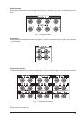
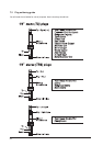
*
Break the normalizing on this bay.
**
Tie lines: usually, in a MIDI setup, racks and keyboards etc. are scattered around the control room. Plugging
these directly into the front of the patchbay would result in Spaghetti Junction. Instead, it is better to connect
TIE LINE jacks to wall boxes strategically positioned near to where MIDI hardware congregates.
***
Its always good to have a few 4-way links around for splitting signals up to 3 ways (one in, three out). E.g.
one tape track has four different instruments on it. Patch the DIRECT out of its CHANNEL into a 4-way split,
returning to a further 3 channels via LINE INPUT. Set up each of the paralleled 4 channels for one instrument,
and use mutes (preferably MIDI controlled) to mute the 3 unwanted channels at any one time).
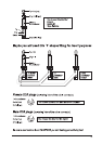
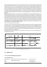
+ Break the NORMALIZING LINKS on positions 21 - 24. Note also that the MIX-B outputs are
adjacent to the aux sends. This is because one of the two functions of MIX-B (source switches
set to CHANNEL) is to provide an extra stereo aux send.
+ You can treat MIX-B as two mono sends using GAIN for level and PAN for blending. Setting pan
to the center will give a 50/50 ratio of the aux 7 and aux 8 effect, hard left 100% aux 7, etc.
****
Break NORMALIZING LINKS here. If youve got more than 5 or 6 stereo dynamics/EQ processors, you might
spill over onto another dedicated bay, or alternatively have to find some suitable extra space somewhere else
in the patchfield. Remember, most dynamics processors also have sidechain/KEY inputs, and therefore
require 3 holes per channel.
+ Enhancers are usually applied across INSERTS like compression and EQ etc., but most
BEHRINGER enhancers have a SOLO mode, in which they can be addressed via an aux send
and blended back into the main mix like any other reverb.