


35
11. IMPEDANCES AND TUNING
Electronic inputs tend to have impedances measured in tens of kiloOhms. Outputs, on the other hand, are
generally two or three orders of magnitude less. This is just as well, otherwise a signal at an output might find
that the line of least resistance is the limit of the preceding unit.
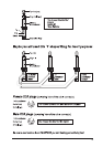
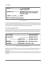
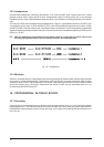
In the patchbay section I recommended that you parallel the MAIN MIX output of the EURODESK MX9000
into all 2-track recording inputs. It would not do any harm to buffer each output from the primary one (i.e. that
feeding into your most expensive DAT recorder or 1/2" mastering machine) with a 470 Ohm resistor. Cassette,
DAT and reel to reel recorders input impedances should be similar, but just in case they arent, it is better to
add a fraction of a dB of thermal noise to the inputs of the secondary recorders in the shape of a resistor, rather
than having an unusually low impedance input grabbing most of the signal. Another neat idea is to parallel the
Monitor L/R output via a 47 kOhm resistor pair. Now you can safely connect e.g. a tuner to either extra hole,
without shifting the stereo image (this would happen if a low impedance tuner input was connected directly
across one side of the monitor output). Now, whenever you monitor an instruments input level with the PFL/
SOLO function, you can check its tuning also. That should impress the customers. Especially those using
old, unstable, but very desirable analog synths.
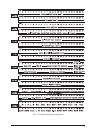
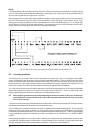
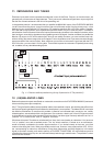
Fig. 11.1: Resistor-buffered parallel wiring for bay 8 (see section 8 The patchfield)
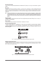
12. (UN)BALANCED LINES
Balanced inputs and outputs are offered on most audio connections on the EURODESK MX9000 (inserts and
direct outs being the major exceptions).
Why? Though all audio cables (except speaker cables) have earthed screens, the shielding they afford from
the electromagnetic garbage that permeates the atmosphere is never perfect. The balanced line is a simple
but effective mechanism to overcome this problem. Instead of one insulated audio conductor, two, usually
twisted together, are contained within a single screen. One conductor, wired to pin 2 of an XLR-type connector
by international convention (after decades of total confusion!) carries a signal variously referred to as hot or
positive. Pin 3 is wired to the cold or negative conductor.
What does this mean? Consider an unbalanced line. Now, thats much easier to understand. You have one
hot or positive core, and an earthed screen. The hot wires waveform, if looked at on an oscilloscope,
would be directly correlated to the audio signal waveform. If you looked closely at the trace, youd see
random noise along the X axis. What you probably wouldnt see, however, is any superposition of 50, 100 Hz,
etc. corresponding to mains hum interference, since these frequencies would be tangled up in the audio
signal (to spot them visually youd need to perform a FOURIER TRANSFORM). AC mains frequency and its
overtones are picked up by any wire, and some will always leak through a cable screen. The question is, when
does it become audible?