41
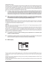
Channel 24 is of course the MIC input. A compressor might be patched into the channel 24 insert. Keep this
channel free until the mix absolutely demands its services, just in case you want to add in any last minute
singing, or any last minute anything!
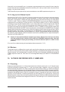
The B-channel line inputs (tape returns) can accomodate even more MIDI expanders and synths, etc.
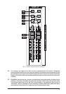
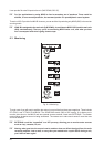
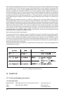
14.4 Lining up record/sample inputs
Set the relevant TAPE OUTPUT and INPUT switches (located at the rear of the console) to match the operating
level of your 8-track (consult manual, phone manufacturer, or simply suck & see to find which setting
works best). The samplers variable input gain range should be more than wide enough to accept either
-10dBV or +4 dBu. There is no oscillator in the EURODESK MX9000, but you can use a simple unmodulated
sustained tone from a keyboard. Choose one around 1 kHz (B above middle C is 997 or 1002 Hz depending
on whether you are using the tempered scale or just tuning: either way its close enough for jazz). Set the
channel EQ to OFF, and line up the channel according to the Setting up procedure (section 13.1). Route
this signal to all subgroups and adjust the SUBGROUP OUTPUT FADERS until the bargraph meters read
0dB. Now put the recorder into INPUT mode on all channels, and the sampler into SAMPLE mode. If the tape
operating level switches are correctly set, then 0 dB on the subgroup output meters should also show 0dB on
the tape recorders input meters. A discrepancy of +/-14 dB indicates a wrong operating level selection.
Small discrepancies may be taken up by the SUBGROUP FADERs, though a better solution would be to get
the multitrack, properly aligned. (Refer to multitrack manual and/or qualified personnel.) Adjust the samplers
input level until it also reads 0 dB.
+ Beware of inaccurate/uncalibrated sampler input meters. Work out how hard you can safely
drive the samplers input, reference this to 0 dB on a EURODESK subgroup meter, then take
note of the samplers input gain pot setting. (Or use soft adhesive tape etc. to hold it in one
position.)
(For more info on digital metering and associated problems see section 13.2.3.)
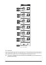
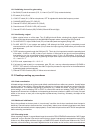
14.5 Mixdown
The situation here is no different from record, really, save that the subgroups may now be routed directly to
the main mix (L/R) bus (S35 to 38) for easier mixing. Remember, you started off with the tape returns coming
up on A-channels 1 to 8, therefore there is no need to flip them. You will probably (definitely) be running lots
of MIDI sequencer tracks live. Take care not to encourage MIDI delays (see section 22 SEQUENCING
LIVE).
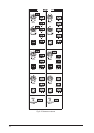
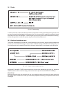
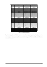
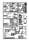
15. 16-TRACK RECORDING WITH 2 SAMPLERS
15.1 Recording
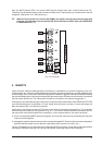
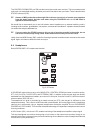
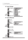
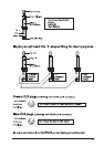
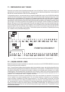
Subgroup outputs/tape sends 1 to 16 should be wired to the multitrack record inputs 1 to 16. Sampler inputs
should be connected to subgroup outs 5, 6, 7 and 8 via custom-made Y-adaptors. Lining up is as per the
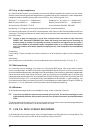
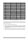
previous example (see section 14.3). When choosing which outputs where to assign, you have to consider that
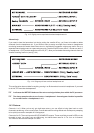
you have got maybe 16 tape and 16 or 20 sampler outputs to accommodate onto 24 A-channels (and 24 B-
channels)! Wed suggest all audio tape tracks be returned on A-Channels, while at least one stereo output from
a sampler is also brought back on a pair of A-channels for flying in (a sampler can pick up e.g. chorus vocal
and drop it into all choruses, or sample a particularly nifty bit of flanging on a drum loop etc.; then lay the
effected loop back to tape, without re-patching). Most other sampler outputs and MIDI keyboards which need
to be heard but not recorded can be assigned to B-channels. The remaining six or so A-channels may then be
used for overdubs.