


50
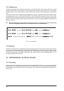
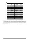
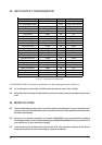
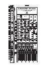
23. INPUT/OUTPUT CONFIGURATION
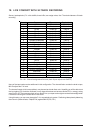
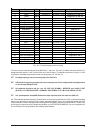
Nominal level Balanced Attenuation
EURODESK internal +4 dBu - -
XLR microphone input - Yes Trimpot / PAD switc
h
Line A input +4 dBu Yes Trimpot
Line B / tape input +4 dBu / -10 dBV Yes Gain switch
Aux sends +4 dBu No Pot
Aux returns 0 dBu No Pot
MIX-B output +4 dBu No Pot
Subgroup output +4 dBu / -10 dBV Yes Gain switch
Main mix 1/4" jack +4 dBu No Fader
Main mix XLR +4 dBu (max. +28 dBu) Yes Fader
2-track out RCA +4 dBu No Fader
2-track in 1/4" jack / RCA +4 dBu No No
External input +4 dBu No No
Channel insert out +4 dBu No No
Channel insert in +4 dBu No No
Channel direct out +4 dBu No Fader
Subgroup insert out 0 dBu No No
Subgroup insert in 0 dBu No No
Main mix insert out 0 dBu No No
Main mix insert in 0 dBu No No
Control room out +4 dBu No Pot
Studio out +4 dBu No Pot
Meter / analyzer out +4 dBu No No
Fig. 23.1: Input/output configuration
The EXPANDER PORT inputs have a nominal level of -2 dBu (subgroup/mix) and +2 dBu (aux).
+ All variable gain circuits offer +15 dB (except aux returns, which offer +20 dB).
+ All balanced jack sockets are automatically unbalanced when using an unbalanced jack patch
lead!
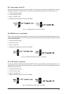
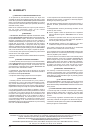
24. MODIFICATIONS
+ These modifications require you to do some soldering. Attempt only if you are experienced in
using an iron on PCBs. Otherwise, refer to qualified personnel. After modification the warranty
becomes discretionary.
+ Excuse us for repeating ourselves once again: BEHRINGER is not responsible for anything
what happens after you start disassembling your EURODESK MX9000. Don't even think of it, if
you make much of your warranty privileges.
+ Links should not be threaded into holes on the PCB. They should be soldered to the tinned
areas around the holes, and bowed slightly upwards in between.