


5
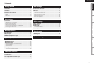
Getting Started Connections Basic Operations Specifi cations Troubleshooting
Effector Function Fader Start UtilityUSB
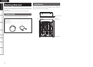
Getting Started
ENGLISH
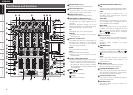
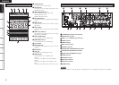
Q5
Effect ON/OFF button
Sets the EFX effects to ON/OFF.
Q6
Channel EFX SEND button
The various set effects can be obtained for the
channel audio signal.
Multiple channels can be selected.
Q7
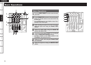
Channel CUE buttons
Pressing in any or all of CUE buttons routes the
respective source to the headphone and meter
cue sections. When the CUE button is pressed
multiple times, the channels selected by the
CUE button are mixed.
•
The SOLO mode with no signals mixed can
also be selected as a preset.
Q8
CROSSFADER ASSIGN switches
A, B:
The channel source is assigned to A or B of the
Crossfader.
THRU:
Select when you don’t assign the channel
source into the Crossfader.
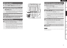
Q9
CROSSFADER
Controls the relative output level from the
summed A and B Mixes. When the fader is
at its far left, only the A Mix is heard from the
Outputs. As the fader is moved toward the
right, the amount of B Mix is increased and the
amount of A Mix is decreased. When the fader
is centered, equal amounts of A and B Mixes are
routed to the Outputs. Fully right is all B Mix at
the Outputs.
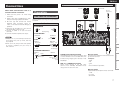
W0
Channel input fader (CH FADER)
Controls the level of the selected Input.
W1
HEADPHONE output jack
Accepts 1/4” stereo headphone plugs.
W2
HEADPHONE level control
Adjusts the volume for the headphones.
W3
HEADPHONE PAN control
This is used to adjust the balance between the
CUE sound and the master sound which are
monitored using the headphones.
W4
SPLIT CUE button
There are two headphone monitor modes.
SPLIT CUE OFF:
The cue signals and master signals can be
monitored in stereo.
SPLIT CUE ON:
The monaural cue signals are heard through
the left channel of the headphones, and the
monaural master signals through the right
channel.
W5
CROSSFADER CONTOUR control
Allows adjusting the “shape” of the Crossfader
response from a gentle curve for smooth, long
running fades, to the steep pitch required for top
performance cut and scratch effects.
W6
CH FADER CONTOUR control
Adjusts the volume curve response of the
channel fader.
W7
CH FADER START switch
This function will start the performance of CD/
Media Player with Ch. Fader automatically is
ON/OFF.
W8
CROSSFADER START switches
Use this to switch the Crossfader Start function
ON and OFF.
W9
MIC SEND LEVEL control
This is used to adjust the level at which the mic
signals are sent to the master output.
E0
Mic EFX INS button
This button enable the various effects to be
obtained for the mic input signals.
E1
MIC EQ controls
Adjusts the frequency of the mic input.
E2
DUCKING ON/OFF button
• Use this to switch the Talk Over function ON
and OFF. (ON/OFF is cyclic)
• When the button is lit, level of signals except
Mics is attenuated.
• The ducking attenuation level can be adjusted
in the “UTILITY” mode.
E3
MIC1, MIC2 TRIM controls
Adjusts the level of the Main Mic input.
E4
MIC1, 2 buttons
When the button’s LED is lighted, the mic
signals take effect.
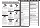
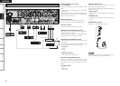
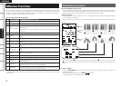
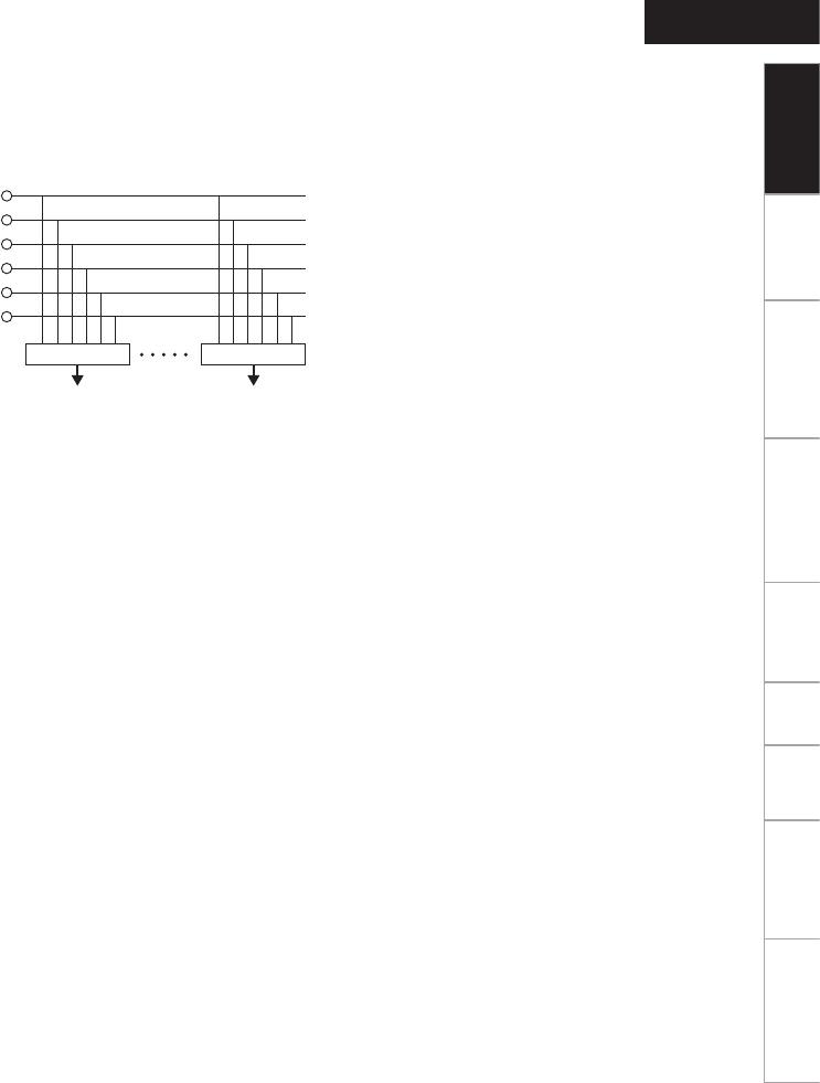
E5
SOURCE SEL LN1/LN2/LN3/LN4/USB/P1–4
controls (channel input selector)
These enable any of six inputs to be selected
for each of the channels. The same input can be
selected for more than one channel.
LINE1
SOURCE SEL
CH1 CH4
SOURCE SEL
LINE2
LINE3
LINE4
USB 1/2 - 7/8
USB P1 - P4
The desired USB source from USB P1–P4 can
be selected from USB 1/2–7/8 and DVS from the
utility mode preset control.
E6
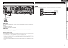
CD/PHONO line input selector buttons
These enable the line input of each channel to
be selected as CD or PHONO.
CD:
Rear panel LINE1–4 CD terminal input
PHONO:
Rear panel LINE2–4 PHONO terminal input
•
LINE1 is only for the CD terminal input.
E7
Channel input LEVEL controls
These are used to adjust the levels of the
selected inputs.
E8
MIDI layer selector buttons
When these buttons are set to ON, the controls
of the selected channels function as MIDI
controllers.
E9
Channel isolator EQ controls (HI, MID, LOW)
These are used to change the frequency
response of the selected inputs.
At the center position, the frequency response
is fl at.
At the –∞ position, the frequencies of all the
bands are cut off completely.
R0
CH LEVEL meter
Displays the input level after adjusted with
LEVEL E7 and Source EQ E9 controls.
R1
MASTER BALANCE control
Adjusts the L/R balance of the MASTER output.
R2
L/CUE, R/PGM master level meter
One of two modes can be selected for display
on this meter.
SPLIT CUE OFF:
The master output audio level is displayed.
SPLIT CUE ON:
The right channel master CUE (monaural) and
left channel CUE (monaural) audio levels are
displayed.
R3
SIG/PK indicator
This is the signal/peak meter for the mic input
level.
Off:
No signals input (under –60 dB/FS)
Green:
Signal input (–60 dB/FS to under –20 dB/FS)
Orange:
Suitable signal input level (–20 dB/FS to under
–6 dB/FS)
Red:
Excessively high signal input level (above –6 dB/
FS)
R4
MIDI button
Pressing this button makes the EFX control
function as the MIDI controller.
R5
MIDI parameter control
Controlling each button outputs the MIDI
command.
R6
MIDI function buttons (FUNC1/2/3/4)
Controlling each button outputs the MIDI
command. Pressing the MIDI function button
while pressing the MIDI button makes it possible
to switch the MIDI page. Different commands
can be output when the MIDI page is switched.