


88
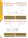
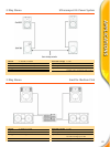
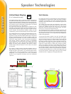
Vertical Beam Shaping
(2- or 3-element line array)
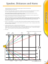
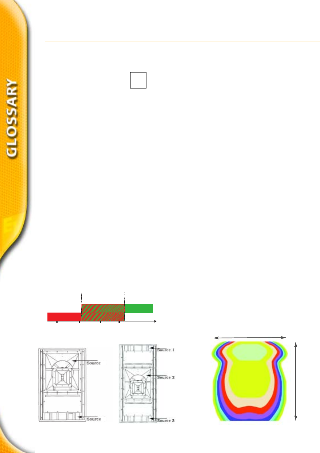
Verticl Beam Shaping (VBS) is a frequency overlap configuration of
the dual-woofer three-way systems of Xi-Series™. It provides the
best directivity improvement, achieved by the vertically spaced low-
frequency sources which flank the mid-bass horn operating alone at
low frequencies and by appropriately overlapping the LF and MB
sources in the mid bass, e.g., 125 to 540 Hz.
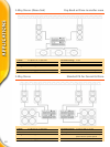
The single-woofer three-way systems may be configured for VBS,
achieved by overlapping the (single) woofer and mid-bass source in
the appropriate frequency ranges. This physical orientation of three
sources, together with appropriate amplitude shading and filter
comibinations, produces vertical directivity control to below 125 Hz.
The resulting interferences of normal overlapped speakers are com-
pletely minimised. The sonic advantages of this combination are
significant. Precisely controlled radiation patterns at low frequencies
prevent reverberant energy in the 125- to 600-Hz range from
degrading vocal fundamentals. The pattern control achieved by this
three-source, single-enclosure “array” prevents the critical distance
from moving “forward” (toward the source) as wavelengths
become significant in size with respect to the radiation device, and
pattern control is lost. This is the case with conventional system
designs. The other primary advantage is that down to 125 Hz,
acoustic output under the enclosure is a full 12 dB or more below
on-axis levels.
This results in greatly improved gain-before-feedback levels on
stage especially in theatres where lavalier microphones are tradi-
tionally used under centre speakers. In conventional systems where
“under enclosure” levels are comparable to on-axis levels, system
intelligibility is even compromised at the source (microphone)
because of poor loudspeaker directivity control and subsequent
“spill over”
.
Vari Intense
®
EV´s unique Vari Intense
®
(VI) technology has a lot of advantages in
most applications of “typical sized” rooms. Vari Intense
®
provides a
rectangular coverage pattern. The unique, patented throat and flare
structure of the VI horn delivers a 6 to 10 dB hotter signal to the
rear of the room.
The resulting even front-to-back SPL eliminates ear strain at the
back of the sitting area and ear pain at the front. One VI horn
replaces two standard systems that reduce costs and eliminates
destructive interference which occurs between long- and short-
throw horns or multi-sourced horizontal arrays.
The downward-aimed horn delivers sound only to the floor plan
where the audience is and provides uniform direct-field SPL and sig-
nificantly reduces the amount of sound reverberating off the ceiling.
This provides an increase in mid- to high-frequency intelligibility of
6 dB in most applications.
To plan with Vari Intense
®
systems is very easy. The height of the
room defines the size of the floor plan covered with one speaker.
The area covered would be a width coverage of two times the
height of the ceiling and depth, or throw, three times the height of
the ceiling. Therefore a Vari Intese
®
speaker mounted centrally, par-
allel to the floor, at a height of 3 meters, would cover a room with
equal SPL, 6 meters wide by 9 meters long. Aiming the speaker
down by 15 degrees at the same 3 meter height will produce an
even floor plan SPL that is 3 meters wide by 6 meters long and tilt-
ing it back by 15 degrees, at the same height, produces a floor plan
SPL of 6 meters wide by 15 meters long. Normally the loudspeaker
is mounted approximately 0.6 to 0.8 times the height back from
the first row and has a nominal angle of the top of the enclosure
parallel to the floor or slightly (2 to 3 degrees) tilted back.
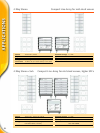
3-ELEMENT
22
11
2-ELEMENT
2 times height
covered floor plan of a VI horn
3 times height
Speaker Technologies
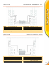
50
100 hz
200
400 hz
F
Overlap Zone
For VBS
LF - SOURCE 1 + 3LF - SOURCE 1 + 3
MB - SOURCE 2MB - SOURCE 2
VBS