


Euphonix System 5 Installation Guide System 5 Components
39
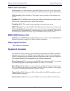
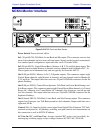
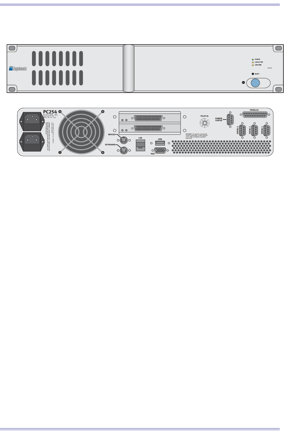
PC254i Interface Computer
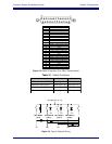
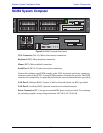
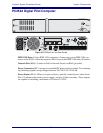
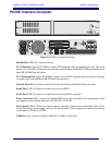
Figure 3-7 PC254i Front and Rear Panels
Parallel Port (DB-25): Currently unused..
TCC Main Port (Lower DC-62HD): Connect TCC breakout cable (provided) to this port. This cable
breaks out to four DB-15 connectors that provide control hookup for the MC524 Monitor Interface and
three ML530 Mic/Line Interfaces.
TCC Extension Port (Upper DC-62HD): Connect a second TCC breakout cable (provided) to this port
to connect up to four additional ML530 Mic/Line Interfaces.
Network Port (RJ45): Connect to the EuCon Network Switch via the RJ45 cable (provided).
Serial Port 1 (DE-9):Connect to control port on first SH612.
Serial Port 2 (DE-9):Connect to control port on second SH612 (optional)
Power Connectors (IEC): Accepts two standard IEC power cords (provided). Two autoranging switch-
ing supplies accept voltages between 100–240 VAC, 50–60 Hz.
Power Status (DE-9): Offers two open-collector, optically-isolated power status feeds. Pins 1/2 ref-
erence the primary power supply, and pins 3/4 the secondary. These outputs are capable of switching
a maximum of 20 mA at 24 VDC.
USB Port (any): Connect to MOTU MIDI I/F via USB A-to-B cable.
INTERFACE PILOT COMPUTER
PC
254i